background image

Application planning 


4.1 Installation site 


SMD 18101 CS / SMD 18101 CP / SMD 18101 D 

4-2


Instruction Manual, 11/2005, A5E00472377A-002 

Summary of Contents for SMD 18101 CP

Page 1: ...display SOLUTIONS SOLUTIONS 18 Gray Scale Flat Panel Display SMD 18101 CS SMD 18101 CP SMD 18101 D Instruction Manual Version 11 2005 ...

Page 2: ......

Page 3: ...g 6 Commissioning 7 Operation 8 Maintenance service and disposal 9 Fault diagnostics 10 Technical data 11 Dimension drawings 12 Appendices A LC displays for medical diagnostics 18 Gray Scale Flat Panel Display SMD 18101 CS SMD 18101 CP SMD 18101 D Instruction Manual 11 2005 A5E00472377A 002 ...

Page 4: ...missioning and operation of a device system may only be performed by qualified personnel Within the context of the safety notes in this documentation qualified persons are defined as persons who are authorized to commission ground and label devices systems and circuits in accordance with established safety practices and standards Prescribed Usage Note the following Warning This device may only be ...

Page 5: ...1 6 2 Connection cover 6 2 6 3 Cable entry via stand 6 2 6 4 Summary of signals and connections 6 3 6 5 Signal connections and DIP switches 6 3 6 5 1 Signal connections 6 3 6 5 2 DIP switch 6 4 6 6 Connecting the signal cables 6 4 6 7 Connecting the line cord 6 6 6 8 Service interface 6 6 7 Commissioning 7 1 7 1 Note on commissioning 7 1 7 2 Control elements and power switches 7 1 7 2 1 Switching ...

Page 6: ...1 Technical data 11 1 11 1 Graphic display 11 1 11 2 Power supply 11 1 11 3 Electronics 11 2 11 4 RGB input 11 2 11 5 Video inputs 11 3 11 6 Control and connection elements 11 3 11 7 Mechanical design 11 4 11 8 Climatic conditions 11 5 11 9 Mechanical requirements 11 5 11 10 Safety specifications 11 6 11 11 Electromagnetic compatibility 11 6 12 Dimension drawings 12 1 12 1 SMD 18101 CS CP 12 1 12 ...

Page 7: ...nts SMD 18101 CS SMD 18101 CP SMD 18101 D Instruction Manual 11 2005 A5E00472377A 002 v A 2 Warranty A 1 A 3 Repairs A 1 A 4 Environmental protection A 1 A 5 Further devices A 1 A 6 Contact address A 1 Index Index 1 ...

Page 8: ...Table of contents SMD 18101 CS SMD 18101 CP SMD 18101 D vi Instruction Manual 11 2005 A5E00472377A 002 ...

Page 9: ...ntended application of the SMD 18101 Gray Scale Flat Panel Display We also point out that the contents of this document are not part of a previous or existing agreement commitment or statutory right and do not change the latter 1 2 Further documentation SMfit ACT Basics The Instruction Manual for the SMfit ACT Basics software is provided on the CD supplied along with the program itself ...

Page 10: ...Introduction 1 2 Further documentation SMD 18101 CS SMD 18101 CP SMD 18101 D 1 2 Instruction Manual 11 2005 A5E00472377A 002 ...

Page 11: ...the warning information is not observed Severe personal injury or damage to property may occur Do not open the unit yourself Certain components inside the unit are at high voltage i e touching these components presents a danger to life Only use a perfect line cord A damaged line cord may result in a fire or electric shock When disconnecting the line cord always do so by holding the plug Do not ins...

Page 12: ...ets with contactor contact 6 For certain applications the video ground can be connected to the protective ground via the additional protective conductor in the plug panel Observe EN 60 601 1 1 IEC 601 1 1 7 Close the plug panel using the provided cover and lock with the screw 8 Mounting information The stability of the display must be ensured following mounting of the stand holder The mounting scr...

Page 13: ...t to impermissible shocks Take care when transporting Use the original packaging The panel in particular should be protected against shocks Notice When touching the panel surface the mechanical contact or an electrostatic discharge may cause a brief disturbance in the picture quality See also Mounting of unit Page 5 1 Cleaning Page 9 1 Installation site Page 4 1 General connection information Page...

Page 14: ...Safety notes SMD 18101 CS SMD 18101 CP SMD 18101 D 2 4 Instruction Manual 11 2005 A5E00472377A 002 ...

Page 15: ...ackaging material for subsequent transport of the display SMD 18101 CS CP Display without stand CD ROM with this Instruction Manual and SMfit ACT Basics SMfit ACT cable SMD 18101 D Display with stand CD ROM with this Instruction Manual and SMfit ACT Basics European power cord US power cord DVI video cable Video cable 15 contact Sub D to 5x BNC SMfit ACT cable ...

Page 16: ...o LCD technology Distortions in the image geometry are not present because of the use of LCD technology The flat panel display provides a flicker free picture even with low refresh rates 60 Hz The display thus fulfills even the strictest ergonomic requirements Modification of gray scale setting In medical applications e g for x rays scanners and nuclear spin tomography where pictures are usually d...

Page 17: ...isplay has two additional analog video inputs and can thus be operated with standard analog video signals PAL NTSC The RGB DVI input and the two video inputs can also be simultaneously connected to signal sources Protective glass The SMD 18101 CP has anti glare protective glass fitted over the top of the LCD panel to protect the surface of the panel against bumps and scratches The space between th...

Page 18: ...Description 3 3 Important features SMD 18101 CS SMD 18101 CP SMD 18101 D 3 4 Instruction Manual 11 2005 A5E00472377A 002 ...

Page 19: ... the manufacturer may be used Avoid reflections on the screen The display has an anti glare surface which is only effective with a clean grease free screen If the screen surface is dirty clean it using a suitable microfiber cloth The display should be positioned so that reflections from lights windows furniture with shiny surfaces or light colored walls do not appear on the screen In order to redu...

Page 20: ...Application planning 4 1 Installation site SMD 18101 CS SMD 18101 CP SMD 18101 D 4 2 Instruction Manual 11 2005 A5E00472377A 002 ...

Page 21: ... of unit Ceiling or stand mounting Several displays can be butt mounted horizontally and vertically The following must be observed when mounting 100 mm hole spacing according to VESA standard Information about the fastening screws Number 4 Thread M4 Strength 8 8 Insertion depth Min 8 mm max 10 mm Torque Max 3 Nm ...

Page 22: ...Assembling 5 1 Mounting of unit SMD 18101 CS SMD 18101 CP SMD 18101 D 5 2 Instruction Manual 11 2005 A5E00472377A 002 ...

Page 23: ...easures All shielding precautions contained in the corresponding EMC guidelines must be observed If these guidelines are not observed interference signals could penetrate and disturb the display operation Information on cable installation Only shielded cables are permitted for all signal connections All cable connections must be screwed or clamped Signal and power cables must not be routed in the ...

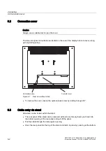
Page 24: ...tches 4XLFN UHOHDVH VFUHZ RQQHFWLRQ FRYHU Figure 6 1 Rear view without stand To remove the cover loosen the quick release screw by rotating through 90 6 3 Cable entry via stand All cables can be routed within the stand The rear panel of the stand can be removed without tools Simply insert your hand into the bottom opening of the rear panel and pull off the panel Pull the cable through the rectangu...

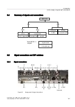
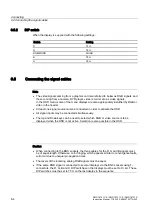
Page 25: ...ignals and connections QDORJ 5 FRQWDFW 9 1 RPSRVLWH 1 6 9LGHR FRQWDFW 0LQL 1 9 9 VLQJOH OLQN 60 5 9LGHR GLJLWDO DQDORJ 6LJQDO QDPHV RQQHFWLRQ W SH SODQDWLRQV RQ GLDJUDP 6 5 Signal connections and DIP switches 6 5 1 Signal connections 9 9 56 1 56 287 9 287 Ω NΩ 9 Ω NΩ 5 0RQR 6 Ω NΩ 5 5 Ω NΩ 9 RPSRVLWH 6 9LGHR Figure 6 2 Arrangement of signal connections ...

Page 26: ...ignal source must be connected in order to activate the OSD All signal inputs may be connected simultaneously The Up and Down keys can be used to select which RGB or video source is to be displayed when the OSD is not active Selection is also possible in the OSD Caution When connecting to the BNC sockets the three cables for the R G and B signals must be of equal length Otherwise color fringing wh...

Page 27: ...he display to the blue and red channels Synchronization possibilities In both types of operating mode it is possible to connect the H and V sync signals separately via the H H V and V sockets or as a composite signal at the H H V socket or as an SoG Sync on Green signal at the G CVS socket VGA Sub D socket Connect VGA cable with 15 contact Sub D connector male for the analog input to the 15 contac...

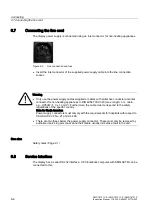
Page 28: ...nlet connector for non heating appliances to DIN 49547 IEC 320 max length 3 m cable e g H05VW F 3 x 1 0 mm Furthermore the cable must correspond to the safety regulations of the specific country Note for North America Power supply connectors must comply with the requirements for hospitals with respect to CSA Std C22 2 No 21 and UL 498 There are two fuses below the power supply connector These must...

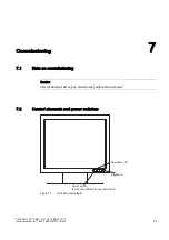
Page 29: ...E00472377A 002 7 1 Commissioning 7 7 1 Note on commissioning Caution Commissioning must only be carried out by authorized personnel 7 2 Control elements and power switches H ERDUG 3RZHU VZLWFK DW WKH UHDU EHKLQG WKH RSHUDWLRQ 2SHUDWLRQ Figure 7 1 Front view with stand ...

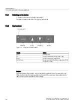
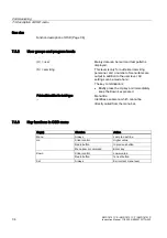
Page 30: ...HW NH RZQ NH 8S NH 0HQX NH 2SHUDWLRQ Figure 7 2 Keypad and status indicator Key s Action Menu Activate OSD Up Hotkey Select RGB analog BNC VGA Down Hotkey Select RGB digital DVI Set 3 x Up Lock or unlock OSD Activate or deactivate PiP if configured in OSD Caution Locking unlocking of the OSD is only permissible for authorized servicing personnel The OSD must be locked if a faulty operation on the ...

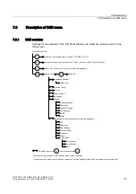
Page 31: ...QWUDVW 306 6WDWXV 26 VHWWLQJV 6KDUSQHVV UHTXHQF SKDVH 6HUYLFHOHYHO RQO DFFHVVLEOH IRU VHUYLFLQJ SHUVRQQHO ODFN OHYHO 83 2 1 0 18 6HOHFWLRQ RI FRQQHFWHG SLFWXUH VRXUFHV 9LGHR 6 9LGHR RU 9 FRQWDFW 9 SOXV 83 ORFN XQORFN 26 RQO IRU VHUYLFLQJ SHUVRQQHO 0DLQ PHQX 6 7 LW 26 9LGHR 3 3 VHWWLQJ RUFH 0RGH RUFH 0RGH HOS KHQ WKHUH LV QR YLGHR VLJQDO D UHGXFHG PDLQ PHQX ZLOO EH GLVSOD HG 6WDWXV DQG 6HUYLFHOHYHO...

Page 32: ...u items are output in addition to the user level All settings can be made here The key combination is Briefly press the Up key and immediately keep the Down key pressed Printed identified in bold type Menu title Identifies a submenu which cannot be directly called from the menu bar 7 3 3 Key functions in OSD menu Key s Situation Action Menu Always Jump to next line Slider control Higher value Radi...

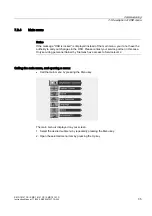
Page 33: ...o not have the authority to carry out changes in the OSD Please contact your service partner in this case Only servicing personnel trained by Siemens have access to Servicelevel 2 Calling the main menu and opening a menu Call the main menu by pressing the Menu key The main menu is displayed on your screen 1 Select the desired submenu by repeatedly pressing the Menu key 2 Open the selected menu ite...

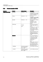
Page 34: ... 6 1 User Selection of the relation of the three signal levels R G and B The relation 1 1 1 is used for optimum display of gray scale pictures the relation 3 6 1 for optimum display of color pictures When selecting User the black level correction set in the Black level menu is activated for the gray scale picture Black level You can correct the black level boosting in this menu A gray scale test p...

Page 35: ...xels Fill to aspect ratio The picture is zoomed to the maximum screen area with retention of the aspect ratio Position Zoom U Zoom only with analog mode and PIP off Fill to square The picture is zoomed to square format Source U BNC DVI Digital Video S Video VGA Select source for main display Select by pressing the Menu key and activate by pressing the Up key Use the Source menu to select the pictu...

Page 36: ... menu for the RGB input or video input is displayed depending on the selected picture source These differ in the first three menu items Frequency Slider control range depends on connected video signal Phase Slider from 0 255 Frequency phase only for RGB picture source Set the frequency and phase of the input signal in the Frequency phase submenu Frequency phase You can optimize the sharpness by pr...

Page 37: ...ilable The PIP window can be shifted in a horizontal and vertical direction Caution Do not use the top left position PIP position 0 0 as the quality of the PIP picture cannot be ensured Brightness The brightness of the PIP window can be set Contrast The contrast of the PIP window can be set Video PIP setting PIP advanced setting Saturation The color intensity of the PIP window can be set PIP sharp...

Page 38: ...light value when changing the gamma curve On the setpoint of the factory adjustment is used as the new backlight value when changing the gamma curve Off the backlight value is retained when changing the gamma curve Select display function A gamma curve from a list of five curves The five gamma curves in the selection list can be set individually using SMfit ACT Calibration The factory calibration ...

Page 39: ...actory set and need not be readjusted User Settings In this menu settings can be stored and reset Reset User settings All automatically stored timing data is deleted Custom settings number 1 5 Custom settings can be saved here A total of five custom settings can be generated The digit is the code number for the memory location Save custom settings Press the Up key to save the current picture setti...

Page 40: ...s 2 If the video source and the connections are OK and if the test pattern is displayed perfectly the fault must be searched for in the video input of the monitor The test patterns can also be used to check the panel quality Proof of the contrast with gray scales and color channels independent of picture picture program graphics card and connectors Complete writing of all pixels on the display sur...

Page 41: ...ed If one of these parameters changes the display treats it as a timing change and initiates resynchronization via an Auto in progress To prevent this happening as a result of each and every minor signal disturbance the value representing the permissible number of faulty or changed frames should be increased in the case of unstable signal sources Disadvantage The higher the tab setting the longer ...

Page 42: ...ownloading of firmware SerialBus Enable disabled The same applies here as to the serial interface Bus Address Slider from 0 10 Definition of bus address for display H Scaler clip Slider from 0 100 Permits adaptation of the side ratio The picture can be expanded or compressed in the horizontal direction It is not possible to store the H Scaler clip in PIP mode Force Mode Force Mode is a tool for se...

Page 43: ... with older medical equipment Such a timing can be entered using the Force Mode functions Force Mode 1 or determined step by step Force Mode 2 Note Only one timing can be saved Force Mode cannot be used to save multiple timings 7 3 6 1 Force Mode 1 Force Mode 1 is used to enter timing data that has already been determined Notice Saving of data only with Force The timing data are only entered into ...

Page 44: ...ecute Force command Define resolution The following steps should only be carried out if the image is unrecognizable 1 Enter the horizontal and vertical resolutions of the image signal in the first two data fields This is the start value for step by step optimization Therefore estimated values can also be entered If no value is known enter 1280 x 1024 for the display resolution 2 Select Mode 3 3 Ex...

Page 45: ... Vertical resolution This range is displayed in black and centric on the display The inactive resolution range is the unused range between the active resolution and the maximum display resolution of 1280 x 1024 This range is displayed in gray in Force Mode FWLYH UHVROXWLRQ UDQJH QDFWLYH UHVROXWLRQ UDQJH 6037 WHVW SDWWHUQ To match the active resolution range to the actual video signal resolution yo...

Page 46: ...gs Optimum picture quality Notice To achieve optimum picture quality the display must be operated with a graphics resolution of 1280 x 1024 pixels The corresponding setting for the graphics card must be made in the operating system See also Graphic display Page 11 1 7 4 1 Adjusting the graphics card As with a CRT monitor the display also has certain limits e g maximum resolution and image refresh ...

Page 47: ...digitizer is matched to the respective picture source Position When carrying out the fine adjustment ensure that all pixels of the picture appear on the active surface of the display This can be checked by shifting in the horizontal and vertical directions When shifting the picture horizontally by one pixel one column must disappear in the direction of movement and a dark pixel column must simulta...

Page 48: ...ed out using the SMTE test pattern Adjust the following parameters in the specified sequence Adjust the brightness such that the smaller square with 5 brightness is visible in the black square 0 brightness Adjust the contrast such that the smaller square with 95 brightness is visible in the white square 100 brightness To adapt the luminosity to the ambient lighting adjust the backlight brightness ...

Page 49: ...made using the display keys These are therefore locked for certain applications Settings must only be changed by authorized personnel Notice Keyboard locked If the keyboard is locked contact the service department in order to unlock it and to make the settings 8 2 Switching on the display Following commissioning operation is limited to switching on and off Switch on the device using the power swit...

Page 50: ...CP SMD 18101 D 8 2 Instruction Manual 11 2005 A5E00472377A 002 8 3 Control elements H ERDUG 3RZHU VZLWFK DW WKH UHDU EHKLQG WKH RSHUDWLRQ 2SHUDWLRQ Figure 8 1 Front view with stand 6HW NH RZQ NH 8S NH 0HQX NH 2SHUDWLRQ Figure 8 2 Keypad and status display ...

Page 51: ...water drops immediately extended contact with water discolors the surface Clean the front panel when dirty using a microfiber cloth and if necessary a cleaning agent Only clean housing parts using the recommended cleaning agents The entire display must only be disinfected using the tested disinfectants Recommended cleaning and disinfectants Agent class Tested cleaning agents and disinfectants Furt...

Page 52: ...illed water Impermissible cleaning agents and disinfectants Agent class Tested cleaning agents and disinfectants Peroxide compounds Perform Dismozon pur These cleaning agents and disinfectants can bleach the paint after a longer period of application See also Safety notes Page 2 1 9 2 Disposal Caution The display must be properly disposed of as electrical waste Its CCFL tubes contain 21 mg of merc...

Page 53: ...o or sync signal Check video cable Sync cable wrongly connected Interchange sync cables No picture appears on the display operation LED on Video source not supplying a signal Check video source Fuzzy picture interference in vertical lines Scanning frequency or phase incorrectly set Adjust frequency and phase Picture is without contrast Graphics card only sends green signal Switch over from RGB MON...

Page 54: ...Fault diagnostics SMD 18101 CS SMD 18101 CP SMD 18101 D 10 2 Instruction Manual 11 2005 A5E00472377A 002 ...

Page 55: ...ixels landscape Pixel spacing 0 28 mm x 0 28 mm Horizontal viewing angle Typically 85 Vertical viewing angle Typically 85 Backlight 6 CCFL cold cathode fluorescent lamps Picture brightness Min 610 cd m Typically 700 cd m Delivery state 400 cd m when using the video standard 1280 x 1024 75 Hz VESA Lifetime of backlight Min 30 000 hours Typically 50 000 hours lifetime brightness 305 cd m applies to ...

Page 56: ...og nominal 0 1 0 Vmax into 75 Ω Sync pulses on R and B picture and blanking signals Permitted DC voltage superimposed on picture and picture blanking signals Must not fall below or exceed 1 V 2 V at the RGB picture and blanking inputs Synchronism signals S 1 H V SYNC separate in the combinations H V with TTL level into 2 kΩ H V with TTL level into 2 kΩ S 2 C SYNC separate in the combinations C SYN...

Page 57: ...xel Blue right subpixel Digital Signal DVI D 1 0 single link Signal input via DVI I connector 11 5 Video inputs Video inputs S Video via Mini DIN socket 4 contact Composite via BNC socket Standards PAL 625 lines 50 Hz NTSC 525 lines 60 Hz 11 6 Control and connection elements Front side 4x keys for OSD menu and picture source selection 1x operation LED Rear side 1x power switch Protected by a cover...

Page 58: ...1 CS Order no 6GF6221 2CD13 Supplied with stand No Protective glass No Weight 6 7 kg Weight incl packaging 8 0 kg Dimensions W x H x D in mm 410 x 338 x 95 SMD 18101 CP Order no 6GF6221 2CD19 Supplied with stand No Protective glass Anti glare glass sheet space between glass sheet and panel is sealed against dust Weight 7 3 kg Weight incl packaging 8 6 kg Dimensions W x H x D in mm 410 x 338 x 95 S...

Page 59: ...orage packed Temperature range 20 C 60 C ambient temperature Temperature gradient Max 5 C h no condensation Relative humidity 10 90 at 25 C Air pressure 674 1050 hPa 11 9 Mechanical requirements Operation Vibration To EN 60068 2 6 10 58 Hz at 0 075 mm deflection 58 500 Hz at 10 m s Shock To EN 60068 2 29 150 m s 6 ms Packed unit original packaging Vibration To EN 60068 2 6 5 9 Hz at 3 5 mm deflect...

Page 60: ... 11 11 Electromagnetic compatibility Radio interference voltage interference noise EN 60601 1 2 Voltage fluctuation EN 610004 11 Burst on power cables EN 61000 4 4 1 kV Surge on power cables EN 61000 4 5 1 kV symmetric 2 kV unsymmetrical Static discharge on casing parts ESD EN 61000 4 2 8 kV air 4 kV contact RFI EN 61000 4 3 800 MHz 1000 MHz 10 V m 80 AM 1 kHz Low frequency and static magnetic fie...

Page 61: ...SMD 18101 CS SMD 18101 CP SMD 18101 D Instruction Manual 11 2005 A5E00472377A 002 12 1 Dimension drawings 12 12 1 SMD 18101 CS CP 12 1 1 Front view HQWHU RI JUDYLW FWLYH GLVSOD DUHD ...

Page 62: ...Dimension drawings 12 1 SMD 18101 CS CP SMD 18101 CS SMD 18101 CP SMD 18101 D 12 2 Instruction Manual 11 2005 A5E00472377A 002 12 1 2 View from left 12 1 3 Rear view ...

Page 63: ...Dimension drawings 12 2 SMD 18101 D SMD 18101 CS SMD 18101 CP SMD 18101 D Instruction Manual 11 2005 A5E00472377A 002 12 3 12 1 4 Plan view 12 2 SMD 18101 D 12 2 1 Front view ...

Page 64: ...Dimension drawings 12 2 SMD 18101 D SMD 18101 CS SMD 18101 CP SMD 18101 D 12 4 Instruction Manual 11 2005 A5E00472377A 002 12 2 2 View from left ...

Page 65: ...Dimension drawings 12 2 SMD 18101 D SMD 18101 CS SMD 18101 CP SMD 18101 D Instruction Manual 11 2005 A5E00472377A 002 12 5 12 2 3 Rear view 5 0 DEOH JODQG DEOH JODQG 12 2 4 Plan view 5 5 ...

Page 66: ...Dimension drawings 12 3 Display stand SMD 18101 CS SMD 18101 CP SMD 18101 D 12 6 Instruction Manual 11 2005 A5E00472377A 002 12 3 Display stand 12 3 1 Front view DEOH JODQG ...

Page 67: ...Dimension drawings 12 3 Display stand SMD 18101 CS SMD 18101 CP SMD 18101 D Instruction Manual 11 2005 A5E00472377A 002 12 7 12 3 2 View from left r r r ...

Page 68: ...Dimension drawings 12 3 Display stand SMD 18101 CS SMD 18101 CP SMD 18101 D 12 8 Instruction Manual 11 2005 A5E00472377A 002 ...

Page 69: ...s These warranty conditions in the contract are neither extended nor limited by the contents of this publication A 3 Repairs In this context please contact your distributor from whom you purchased the product Repairs must only be carried out by authorized service centers A 4 Environmental protection When disposing of the device the requirements and laws in the respective country must be observed A...

Page 70: ...Appendices A 6 Contact address SMD 18101 CS SMD 18101 CP SMD 18101 D A 2 Instruction Manual 11 2005 A5E00472377A 002 ...

Page 71: ...d protective glass 3 2 D Desktop Desktop version 3 2 Dimensions SMD 18101 CP 11 4 SMD 18101 CS 11 4 SMD 18101 D 11 4 Display Avoid reflections on the screen 4 1 Ceiling or stand mounting 5 1 Cleaning agents and disinfectants 9 1 Minimum distance from other units 4 1 Performance features 3 2 DVI input 3 3 DVI socket 6 5 DVI video cable 3 1 E Electromagnetic compatibility Standards guidelines 11 6 E...

Page 72: ...r supply cable 6 6 Product disposal A 1 Protective glass 3 3 R Relative humidity in operation 11 5 Transport and storage packed 11 5 RGB input 11 2 S Serial interface 6 6 Serial Luminance Meter Adjustment of brightness and contrast 7 19 Serial Spot Meter Adjustment of brightness and contrast 7 19 Service socket See also serial interface 11 3 Shielding measures 6 1 SMfit ACT Basics 1 1 U Universal ...

Page 73: ......

Page 74: ...Siemens AG Automation and Drives Systems Engineering Display Technologies Siemensallee 84 76187 KARLSRUHE GERMANY www siemens com displays Order No A5E00472377A 002 ...

Reviews: