Connecting
6.6 Connecting the signal cables
SMD 18101 CS / SMD 18101 CP / SMD 18101 D
Instruction Manual, 11/2005, A5E00472377A-002
6-5
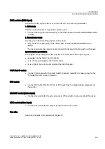
BNC sockets (RGB input)
Connect the video signal to the R, G and B sockets. There are two possibilities:
1. RGB mode
The three color channels of a graphics card are used.
•
Connect the red, green and blue plugs of the video cable, and set the MONO/RGB switch
to RGB.
2. Monochrome mode
Only the green channel of the graphics card is used.
•
Only connect the green plug of the video cable, and set the MONO/RGB switch to
MONO.
The green signal is then also connected inside the display to the blue and red channels.
Synchronization possibilities
In both types of operating mode, it is possible to connect the H and V sync signals
•
separately via the H/H+V and V sockets
•
or as a composite signal at the H/H+V socket
•
or as an SoG (Sync on Green) signal at the G/CVS socket.
VGA Sub-D socket
•
Connect VGA cable with 15-contact Sub-D connector (male) for the analog input to the
15-contact Sub-D connector (female).
DVI socket
•
Connect DVI cable (DVI-D or DVI-I) to DVI input. Only the digital signal is displayed on
the monitor.
Mini-DIN socket (video input)
•
Connect video cable for the sync video input (Y/C signal) to the 4-pole mini-DIN socket.
BNC socket (video input)
•
Connect video cable for the composite input to the Cinch socket.
See also


