Connecting
5.5 Integrating the FC410 with Modbus system
FC410 with Modbus Operating Instructions, 02/2016, A5E33120874-AC
47
Image 5-8
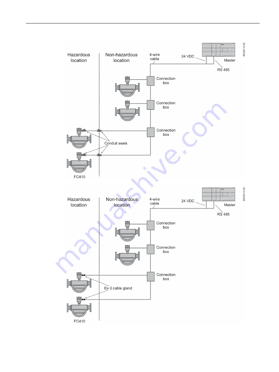
Multidrop configuration in hazardous location
Page 1: ...Operating Instructions Answers for industry 02 2016 Edition Coriolis flowmeters SITRANS FC410 with Modbus SITRANS F ...
Page 2: ......
Page 3: ... AC Introduction 1 Safety notes 2 Description 3 Installing Mounting 4 Connecting 5 Commissioning 6 Functions 7 Alarms and system messages 8 Service and maintenance 9 Troubleshooting FAQs 10 Technical data 11 Spare parts and accessories 12 Dimensions and weight 13 Modbus holding registers A Sensor dimension dependent default settings B Zero point adjustment C CRC calculation D Exception codes E Flo...
Page 4: ... may be operated only by personnel qualified for the specific task in accordance with the relevant documentation in particular its warning notices and safety instructions Qualified personnel are those who based on their training and experience are capable of identifying risks and avoiding potential hazards when working with these products systems Proper use of Siemens products Note the following W...
Page 5: ...tion 25 4 Installing Mounting 27 4 1 Flowmeter installation 27 4 1 1 Installation safety precautions 27 4 1 2 Determining a location 28 4 1 3 Orientation of the device 29 4 1 4 Mounting the flowmeter 32 4 1 5 Hydrostatic testing 34 4 1 6 Mounting a pressure guard 34 5 Connecting 37 5 1 Wiring in hazardous locations 37 5 2 Cable requirements 37 5 3 Safety notes for connecting 38 5 4 Connecting the ...
Page 6: ...meters accessed via drop down menus 64 6 13 Zero point adjustment 65 6 14 Process variables 67 7 Functions 69 7 1 Process values 69 7 2 Zero point adjustment 69 7 3 Low flow cut off 71 7 4 Empty tube monitoring 72 7 5 Process noise damping 73 7 6 Totalizer 75 7 7 Access management 75 7 8 Simulation 76 7 9 Changing Modbus communication settings 77 7 10 Float transmission 77 8 Alarms and system mess...
Page 7: ...sign 99 11 9 Power supply 100 11 10 Basic electrical requirement for master system 100 11 11 Cables and cable entries 101 11 12 Installation torques 102 11 13 Certificates and approvals 102 11 14 PED 103 12 Spare parts and accessories 109 12 1 Ordering 109 12 2 Ex approved products 109 12 3 Replaceable components 110 13 Dimensions and weight 111 13 1 Sensor dimensions 111 13 2 Length matrix 112 13...
Page 8: ...ion 132 A 3 7 Characteristics 133 A 3 8 Simulation 135 A 3 9 Alarms 136 A 3 10 Quality codes for process values 138 B Sensor dimension dependent default settings 139 C Zero point adjustment 141 D CRC calculation 145 E Exception codes 149 E 1 Exception handling 149 F Float definition 151 F 1 Float definition 151 Glossary 153 Index 155 ...
Page 9: ...s contract contains all obligations on the part of Siemens as well as the complete and solely applicable warranty conditions Any statements regarding device versions described in the manual do not create new warranties or modify the existing warranty The content reflects the technical status at the time of publishing Siemens reserves the right to make technical changes in the course of further dev...
Page 10: ... glands SD card with production certificates Quick Start guide CD containing software certificates and device manuals Note Supplementary information Supplementary product and production specific certificates are included on the SensorFlash SD card Note Scope of delivery may vary depending on version and add ons Make sure the scope of delivery and the information on the nameplate correspond to your...
Page 11: ...of the FC410 Coriolis flowmeter has three nameplate types showing the following information product identification product specifications certificates and approvals Note Identification Identify your device by comparing your ordering data with the information on the product and specification nameplates FC410 sensor identification nameplate Product name Sensor product name Serial no Flowmeter serial...
Page 12: ...below xxxxxx Sequential number Encryption Calendar year Y Code 1950 1970 1990 2010 A 1951 1971 1991 2011 B 1952 1972 1992 2012 C 1953 1973 1993 2013 D 1954 1974 1994 2014 E 1955 1975 1995 2015 F 1956 1976 1996 2016 H G 1957 1977 1997 2017 J 1958 1978 1998 2018 K 1959 1979 1999 2019 L 1960 1980 2000 2020 M 1961 1981 2001 2021 N 1962 1982 2002 2022 P 1963 1983 2003 2023 R 1964 1984 2004 2024 S 1965 ...
Page 13: ... and 200 C 392 F max temperature Fluid group Fluid group statement required by PED Wetted material Tube process connection materials Min fluid temperature Minimum fluid temperature Size DN Nominal size Conn Process connection type and size Year of Manufacture Manufacturing year More detailed manufacturing date information is given in the serial number found on the identification nameplate Cal Fact...
Page 14: ...ss range Modbus device address range Manufacturer Manufacturer name and location Country Manufacturing country HW Hardware version FW Firmware version Image 1 3 FC410 Mini Flow Link identification nameplate Note Approval identifications Approval certificates and notified body identifications are available for download at siemens com FC410 sensor approval nameplate QR code Product specific QR code ...
Page 15: ...enic sensor The Australian C tick mark is mandatory on all products FC410 EHEDG nameplate Image 1 5 EHEDG nameplate This nameplate appears on all Hygienic sensors 7ME462 Other label Image 1 6 How to install The QR code provides direct internet connection to The product support portal which includes access to the How to Install YouTube video This example provides that function Product and productio...
Page 16: ...the Siemens homepage where further information on the range of SITRANS F flowmeters may also be found Product information on the internet http www siemens com flow Worldwide contact person If you need more information or have particular problems not covered sufficiently by these Operating Instructions get in touch with your contact person You can find contact information for your local contact per...
Page 17: ...ction assembly and operation These include for example National Electrical Code NEC NFPA 70 USA Canadian Electrical Code CEC Canada Further provisions for hazardous area applications are for example IEC 60079 14 international EN 60079 14 EC Conformity with European directives The CE marking on the device symbolizes the conformity with the following European directives Electromagnetic compatibili t...
Page 18: ... is available on request WARNING Improper device modifications Danger to personnel system and environment can result from modifications to the device particularly in hazardous areas Only carry out modifications that are described in the instructions for the device Failure to observe this requirement cancels the manufacturer s warranty and the product approvals Note CE declaration The CE declaratio...
Page 19: ...Zone 1 in environment For dust Ex ta IIIC T C Da Ex tb IIIC T C Db Zone 20 ta process and ambient temperature limited in comparison with Zone 21 tb Ta 40 C to 60 C Temperature class dependent on the process temperature and the ambient temperatur IECEx FC410 flowmeter can be installed in Zone 1 for gas and Zone 20 21 for dust Certificate IECEx SIR 11 0149X For gas Ex d ia IIC T Ga Gb Ex d IIC T Ga ...
Page 20: ...espect to temperature class for the device when used with potentially explosive gases in a maximum ambient temperature of 60 C are Ta C Maximum Process Temperature per Temperature Class C T6 T5 T4 T3 60 70 70 70 70 55 85 100 100 100 50 85 100 130 130 45 85 100 135 160 40 85 100 135 190 35 85 100 135 200 30 85 100 135 200 If the equipment is placed in a tb environment Zone 21 the maximum process te...
Page 21: ...t the hazardous area EN IEC 60079 14 is considered for installation in hazardous areas Further information and instructions including approval specific special conditions for safe use in Ex applications can be found in the certificates on the accompanying literature CD and at www siemens com FC410 www siemens com FC410 WARNING Laying of cables Explosion hazard Cable for use in hazardous locations ...
Page 22: ...online support portal and can also be found on the documentation disk shipped with the device http www siemens com processinstrumentation certificates Certification documents including calibration report are supplied with each sensor included on the SensorFlash Material pressure test and factory conformance certificates are optional at ordering ...
Page 23: ... such as Chemical Pharma detergents bulk chemicals acids alkalis pharmaceuticals blood products vaccines insulin production Food Beverage dairy products beer wine soft drinks Brix Plato fruit juices and pulps bottling CO2 dosing CIP SIP liquids mixture recipe control Automotive fuel injection nozzle pump testing filling of AC units engine consumption paint robots Oil Gas filling of gas bottles fur...
Page 24: ...onnections at each end via a manifold The sensors are available in AISI 316L stainless steel and Hastelloy C22 The enclosure is made of AISI 304 stainless steel which has a pressure rating of 20 bar 290 psi for DN 15 to DN 50 and 17 bar 247 psi for DN 80 The burst pressure for all sizes is in excess of 160 bar The sensor enclosure can be equipped with a pressure guard or flushed with dry inert gas...
Page 25: ...nnected point to point or in a multidrop network in non hazardous or hazardous locations It can be connected to different hosts for example a PLC system or a PC used as service tool or configuration tool Note Multidrop installations in hazardous locations Multidrop installations in hazardous locations require flameproof conduit seals for each device see illustrations in System configurations Page ...
Page 26: ...s is a mono master system which means that only one master at a time can be connected Unicast communication mode In unicast mode master slave mode the master sends a request to a specific slave device and waits a specified time for a response Image 3 4 Unicast Mode Modbus Frame The Modbus frame is shown below and is valid for both requests and responses Table 3 1 Modbus Frame SLAVE ADDRESS FUNCTIO...
Page 27: ...flow The totalizer is reset on loss of power Empty pipe monitoring Simulation of process values Massflow Volumeflow Density Process media temperature Troubleshooting and sensor checking Use in hazardous locations according to specification 3 5 Theory of operation The Coriolis principle of measurement The flow measurement is based on the Coriolis law of motion Particles moving in a rotating oscilla...
Page 28: ...o accurately measured The flow proportional phase signal from the pickups the temperature measurement and the driver frequency enable calculation and reporting of mass density volume and temperature Digital signal processing DSP The analog to digital conversion takes place in an ultra low noise sigma delta converter with high signal resolution With fast digital signal processing massflow and densi...
Page 29: ...cautions WARNING High pressure hazard In applications with working pressures media that can be dangerous to people surroundings equipment or others in case of pipe fracture we recommend that special precautions such as special placement shielding or installation of a pressure guard or a safety valve are taken when the flowmeter is mounted WARNING Exceeded maximum permissible operating pressure Dan...
Page 30: ...ses and loads from acting on the device WARNING Wetted parts unsuitable for the process media Danger of injury or damage to device Hot toxic and corrosive media could be released if the process medium is unsuitable for the wetted parts Ensure that the material of the device parts wetted by the process medium is suitable for the medium Refer to the information in Technical data Page 99 Note Materia...
Page 31: ...roneous measurements particularly in the density measurement Do not install the flowmeter at the highest point in the system where bubbles will be trapped Install the flowmeter in low pipeline sections at the bottom of a U section in the pipeline Image 4 1 Liquid applications wrong location with trapped air gas Gas applications Vapor condensation or oil traces in the gas may result in erroneous me...
Page 32: ...media in order to measure accurately Orienting the sensor The sensor operates in any orientation The optimal orientation depends on the process fluid and the process conditions Siemens recommends orienting the sensor in one of the following ways 1 Vertical installation with an upwards flow self draining Image 4 3 Vertical orientation upwards flow 2 Horizontal installation tubes down recommended fo...
Page 33: ...plications In 3A and EHEDG certified hygienic applications the flowmeter must be installed vertically as shown in 1 above Installation in a drop line Installation in a drop line is only recommended if a pipeline reduction or orifice with a smaller cross section can be installed to create back pressure and prevent the sensor from being partially drained while measuring Back pressure orifice On off ...
Page 34: ...s Danger of injury or poisoning In case of improper mounting hot toxic and corrosive process media could be released at the connections Ensure that connecting parts such as flange gaskets and bolts are suitable for connection and process media Install the flowmeter in well supported pipelines in order to support the weight of the device Center the connecting pipelines axially in order to assure a ...
Page 35: ...mage 4 7 Non flexible pipes not recommended in vibrating environment Image 4 8 Flexible pipes recommended in vibrating environment Avoid cross talk If operating more than one flowmeter in one or multiple interconnected pipelines there is a risk of cross talk Prevent cross talk in one of the following ways Mount sensors on separate frames Decouple the pipeline using flexible tube or couplings Image...
Page 36: ...ystem 4 1 6 Mounting a pressure guard The sensor enclosure is supplied with two G parallel thread purge ports These ports can for example be used for a pressure guard which can be connected to an automatic shut off valve to stop the flow in case of sensor pipe fracture Note Non hazardous locations only A pressure guard can be applied only in non hazardous locations Note Avoid opening purge ports O...
Page 37: ...ained away from personnel and other plant or equipment Mounting of pressure guard CAUTION Moisture liquids or particles getting into the sensor enclosure All sensors are filled with argon to avoid condensation Ingress of moisture liquids or particles into the sensor may influence the measurement and in worst case inhibit the measuring function Avoid moisture liquids or particles getting into the s...
Page 38: ...NOT touch any of the parts inside the sensor Maximum of 20 mm 0 79 insertion can be accommodated 5 Check that the pressure guard has been correctly mounted and thoroughly tightened torque 80 Nm WARNING Operation in proximity with pressure guards Prevent personal injuries by assuring that operation in close proximity with pressure guards cannot take place ...
Page 39: ...nd one in the non hazardous location WARNING MFL housing Before opening the MFL housing check that No explosion hazard exists All connection leads are potential free 5 2 Cable requirements Cable specifications Only use cables with at least the same degree of protection as the sensor to install the sensor It is recommended to use cables supplied by Siemens A S Flow Instruments Siemens supplied cabl...
Page 40: ...zardous areas Protect unused cable ends in accordance with IEC EN 60079 14 5 3 Safety notes for connecting WARNING Skills Only qualified personnel may carry out work on the electrical connections Use in hazardous locations Before accessing the sensor terminal compartment and application terminal compartment check that No explosion hazard exists FC410 may not be opened if energized A safe access pe...
Page 41: ...plugs The cable screen is physically and electrically terminated within the body of the plug Take care when handling the cable and passing it through cable ducting that the plug is not subjected to excessive tension pulling as the internal connections may be disengaged Note Never pull the cable by the plug only by the cable itself 1 Connect the device using the supplied 4 wire cable with M12 conne...
Page 42: ...he sensor connection white plug from the electronic 4 Loosen the mounting screw using a TX10 Torx driver and remove the electronic from the housing 5 Remove the cap and the ferrule from the cable gland and slide onto the cable 6 Push the cable through the open gland and anchor the cable shield and the wires with the clamp bar 7 Remove the terminal block from the electronic 8 Connect the wires to t...
Page 43: ...nsor cable 11 Restore the flexible strap around all wires 12 Assemble and tighten the cable gland 13 Remove the O ring from lid 14 Reinstate the lid and screw in until the mechanical stop Wind back the lid by one turn 15 Mount the O ring by pulling it over the lid and tighten the lid until you feel friction from the O ring on both sides Wind the lid by one quarter of a turn to seal on the O ring 1...
Page 44: ...rations Page 43 The table below shows the relation between the DIP switch settings and the permissible communication interface set ups Default configuration is EOL active Location of DIP switch The DIP switch is located in the electronic as shown below Image 5 3 DIP switch location all set to ON DIP switch settings for communication set up DIP switch Communi cation set up Switch 1 Switch 2 Switch ...
Page 45: ...ow provide an overview of the major design criteria For further details contact Siemens If the device is integrated in a hazardous location two flameproof conduit seals per device must be installed one at the device in the hazardous location and one in the non hazardous location see System configurations Page 43 5 5 1 System configurations Non hazardous locations The following figures show example...
Page 46: ...Connecting 5 5 Integrating the FC410 with Modbus system FC410 with Modbus 44 Operating Instructions 02 2016 A5E33120874 AC Image 5 5 Multidrop configuration branch in non hazardous location ...
Page 47: ... system FC410 with Modbus Operating Instructions 02 2016 A5E33120874 AC 45 Image 5 6 Multidrop configuration Daisy chain in non hazardous location NOTICE M12 plugged systems Daisy chain multidrop configuration is NOT possible with M12 plugged systems ...
Page 48: ...with Modbus 46 Operating Instructions 02 2016 A5E33120874 AC Hazardous locations The following figures show examples of installations in point to point and multidrop configurations in hazardous locations Image 5 7 Point to point configuration in hazardous location ...
Page 49: ...Connecting 5 5 Integrating the FC410 with Modbus system FC410 with Modbus Operating Instructions 02 2016 A5E33120874 AC 47 Image 5 8 Multidrop configuration in hazardous location ...
Page 50: ...e FC410 must be connected to terminal A on the master host system Terminal B on the FC410 must be connected to terminal B on the master host system This corresponds to a half duplex communication where the slave will only reply to a request from the master This example shows an EMC shielded enclosure for multidrop installation where the connection includes signal and power Cable shield must be gro...
Page 51: ...ly daisy chaining or by short branch cables Note Multidrop examples in this document show a trunk cable with short branch cables Maximum cable lengths The end to end length of the trunk cable must be limited The maximum length depends on the baud rate the cable gauge capacitance or characteristic Impedance the number and types of loads on the daisy chain and the network configuration Note Maximum ...
Page 52: ...Connecting 5 5 Integrating the FC410 with Modbus system FC410 with Modbus 50 Operating Instructions 02 2016 A5E33120874 AC ...
Page 53: ...ected to this device can be operated with high pressure and corrosive media Therefore improper handling of the device can lead to serious injuries and or considerable material damage WARNING Commissioning and operation with pending error If an error message appears correct operation in the process is no longer guaranteed Check the gravity of the error Correct the error If the error still exists Ta...
Page 54: ...rs accessed via drop down menus Page 64 for parameters that do not appear in the menu structure in SIMATIC PDM Note Supported SIMATIC PDM versions The EDD supporting this product is compatible with SIMATIC PDM v 6 0 SP5 HF5 or from v 8 2 SP1 6 5 Commissioning steps In the following it is described how to commission the device with SIMATIC PDM The steps are divided into the following sections 1 Ini...
Page 55: ...ed button 5 If the Use FIFO buffers check box is deselected click to select 6 Set Receiver Buffer and Transmitter Buffer to Low 1 7 Click OK to close out Close all screens and then reboot Updating the Electronic Device Description EDD You can locate the EDD in the SIMATIC PDM Device Library under Devices Modbus Sensors Flow Coriolis Siemens AG SITRANS FC410 Check the product page of our website at...
Page 56: ...click on Networks and Insert New Object Communication Network Click on Assign Device Type and select Modbus Network Click OK two times Your PC is now added to the Modbus Network Right click Modbus Network and select Insert New Object Object Click on Assign Device Type and select Devices Modbus Sensors Flow Coriolis SIEMENS AG SITRANS FC410 Click OK two times Image 6 1 Assigning Modbus device to ne...
Page 57: ...p the COM interface Select Modbus Networks Right click on the object name SITRANS FC410 and select Object Properties Select the Communication tab and configure the Modbus address Image 6 3 Set the Modbus address Click OK 6 8 Configuring a new device Note Clicking on Cancel during an upload from device to SIMATIC PDM will result in some parameters NOT being updated ...
Page 58: ...the device for a simple application Please consult the SIMATIC PDM operating instructions or online help for details on using SIMATIC PDM Access level control The parameters are protected against changes by access level control To gain access select Access Management from the device menu select User and enter the PIN code The default user PIN code is 2457 Quick start Note The Quick Start wizard se...
Page 59: ...ary according to the resolution setting for your computer monitor The recommended resolution is 1280 x 960 1 Click on Read Data from Device to upload Quick Start parameter settings from the device to the PC PG and ensure PDM is synchronized with the device 2 Click on Next to accept the default values Descriptor Message and Date fields can be left blank Image 6 4 Quick start step 1 ...
Page 60: ... via PDM FC410 with Modbus 58 Operating Instructions 02 2016 A5E33120874 AC Step 2 Sensor orientation Step 2 shows an overview of the various recommended installation orientations depending on the application Image 6 5 Quick start step 2 ...
Page 61: ...tart via PDM FC410 with Modbus Operating Instructions 02 2016 A5E33120874 AC 59 Step 3 Sensor connection An FC410 can be ordered with M12 connection or with terminated cable for example conduit connections Image 6 6 Quick start step 3 ...
Page 62: ...0 with Modbus 60 Operating Instructions 02 2016 A5E33120874 AC Step 4 Measurement conditions Configure the measurement conditions for the selected process variables Change Flow Direction if necessary Units are local in PDM Image 6 7 Quick start step 4 ...
Page 63: ...ia PDM FC410 with Modbus Operating Instructions 02 2016 A5E33120874 AC 61 Reduce the sensitivity of the flow measurement signal by clicking on the Pulsating Flow button and selecting the appropriate filter Image 6 8 Filter setting selection ...
Page 64: ...k on Back to return and revise values Apply to save settings offline or Apply and Transfer to save settings offline and transfer them to the device Image 6 9 Quick start step 5 The message Quick Start was successful will appear Click on OK See also Configuring a new device Page 55 6 10 Wizard Zero Point adjustment Open the menu Device Wizard Zero Point Adjustment ...
Page 65: ...djustment FC410 with Modbus Operating Instructions 02 2016 A5E33120874 AC 63 Select Auto Click on Next It is recommended to use the default settings Change the Zero Point Adjustments Settings if necessary Click on Auto Zero Point Adjustment ...
Page 66: ...ers NOT being updated Many parameters are accessed via the online menus in PDM see Parameters accessed via drop down menus Page 64 for the others 1 Launch SIMATIC PDM connect to the appropriate device and upload data 2 Adjust parameter values in the parameter value field then click on Enter The status fields read Changed 3 Open the Device menu click on Download to device then use File Save to save...
Page 67: ... dialog Controlling massflow totalizer Maintenance online dialog Setup of maintenance functions Simulation online dialog Simulation of process values Access Management Possibility to upgrade access level from User to Expert and to change PIN code for Expert level Table 6 2 View menus View menus Description Process Variables online dialog Shows all process values Device Diagnostic online dialog Sho...
Page 68: ...actice zero point adjustment with a by pass line and two shut off devices 2 Establish zero flow for example by closing the shut off valves 3 Wait 1 to 2 minutes for the system to settle and then perform zero adjustment as described in the following steps 4 Select Device Wizard Zero Point Adjustment from the main menu of SIMATIC PDM to perform an automatic zero point adjustment 5 Click Next and the...
Page 69: ...o point adjustment refer to Alarms and system messages Page 79 The system is now ready for normal operation 6 14 Process variables 1 To compare outputs in real time select View Process Variables to see all process values totalizers and loop current 2 Verify that the process values show the expected values Image 6 11 Process variables Trend view Open the menu View Process Variables and click on one...
Page 70: ...Commissioning 6 14 Process variables FC410 with Modbus 68 Operating Instructions 02 2016 A5E33120874 AC ...
Page 71: ... 10 ms 100 Hz update rate synchronous with the DSP update cycle Process value parameters The process values are Massflow MassflowValue kg s Volumeflow VolumeflowValue m3 s Density Density kg m3 Process media temperature FlowMediaTemp C 7 2 Zero point adjustment In the following the automatic zero point adjustment function is described For further details see Zero point adjustment Note Precondition...
Page 72: ... quantity If the flow quantity is extremely small extremely precise measurement is necessary In this case a long zero point adjustment period can be selected for improved zero point adjustment Zero point calculation During zero point adjustment an average value is automatically calculated using the following formula Zero Point Offset Value Average of N flow values xi is an instantaneous flow value...
Page 73: ... Check the validity of the configured standard deviation limit in parameter 2 6 4 Standard Deviation Limit Repeat the zero point adjustment Successful automatic zero point adjustment If the new zero point offset value is valid it is automatically stored as the new zero point for the sensor It remains stored in the case of a power failure Manual zero point adjustment In case an automatic zero point...
Page 74: ...s for setting the empty tube monitoring function are available Empty Tube Detection Modbus address 2129 Empty Tube Limit Modbus address 2127 The empty tube monitoring is activated via the Empty Tube Detection parameter When the empty tube monitoring function is on the massflow volumeflow value is forced to zero if the tube is empty The tube is defined as empty if the measured density value is lowe...
Page 75: ...he function is typically used in environment with Strongly pulsating flow Changing pump speeds Large pressure variations Process noise damping settings Reduce interfering process noise by increasing the setting of the parameter Process Noise Damping Modbus address 2130 Centrifugal pump 1 low Triplex pump 2 Duplex pump 3 Simplex pump 4 Cam pump 5 high The default value is Duplex pump The damping af...
Page 76: ...74 Operating Instructions 02 2016 A5E33120874 AC Image 7 3 Duplex pump 3 default setting Image 7 4 Simplex pump 4 Image 7 5 Cam pump 5 high Note Increased reaction time The reaction time of the sensor increases when the process noise is damped ...
Page 77: ...e occurred Resume Modbus address 2614 the totalizer continues counting the actual measured value Reset Modbus address 2612 the totalizer continues counting based on the last input value for example massflow before the failure occurred Note The totalizer is reset on power failure 7 7 Access management All parameters may be viewed but some are protected against changes by access level control The Ac...
Page 78: ...nction The access level will be set to Read Only mode if the device is powered off 7 8 Simulation Simulation is used for testing purposes typically for checking that the readings of the control system are correct Process value simulation The following process values can be simulated Massflow Modbus address 2764 Density Modbus address 2766 Process Media Temperature Modbus address 2768 Frame Tempera...
Page 79: ...ecommended NOT to use the default address in a multi drop network When setting device addresses make sure that each device has a unique address Replication of addresses may cause abnormal behavior of the entire serial bus and make the master unable to communicate with all slaves on the bus 7 10 Float transmission The Float Byte Order function ensures that the master and slave use the same sequence...
Page 80: ...MM Byte 3 SEEEEEEE Byte 2 EMMMMMMM 0 1 2 3 Byte 0 MMMMMMMM Byte 1 MMMMMMMM Byte 2 EMMMMMMM Byte 3 SEEEEEEE 2 3 0 1 Byte 2 EMMMMMMM Byte 3 SEEEEEEE Byte 0 MMMMMMMM Byte 1 MMMMMMMM 3 2 1 0 Byte 3 SEEEEEEE Byte 2 EMMMMMMM Byte 1 MMMMMMMM Byte 0 MMMMMMMM Factory setting S Sign E Exponent M Mantissa NOTICE Change of float byte order If the float byte order is changed by use of PDM to anything other tha...
Page 81: ...a Contact Siemens customer support for recalibration 15 Invalid compensation data Contact Siemens customer support 17 18 Malfunction in Pickup Amplitude Contact Siemens customer support 23 24 25 Malfunction in sensor driver Contact Siemens customer support 26 Unstable driver oscillation Contact Siemens customer support 27 Massflow out of specification Reduce the flow If the failure continues then ...
Page 82: ... adjustment and repeat adjustment 4 Zero point adjustment failed shown for only 2 seconds Measurement continues with values from last successful zero point adjust ment Improve conditions for automatic zero point adjustment and repeat adjustment 5 Empty Tube Limit exceeded Make sure that the sensor is filled with liquid and that the liquid density is within the specified Empty Tube Limit 6 The sens...
Page 83: ... grounds NOTICE Repair and service must be carried out by Siemens authorized personnel only Note Siemens defines flow sensors as non repairable products 9 2 Maintenance information parameters The basic maintenance parameters are Operating Time Total Since first power up Operating Time Since Power Up Since latest power up 9 3 Service information Service information is information about the conditio...
Page 84: ...ays be returned with the sensor 9 5 Technical support If you have any technical questions about the device described in these Operating Instructions and do not find the right answers you can contact Customer Support Via the Internet using the Support Request Support request http www siemens com automation support request Via Phone Europe 49 0 911 895 7222 America 1 423 262 5710 Asia Pacific 86 10 ...
Page 85: ...ansport and storage observe the following Keep the original packaging for subsequent transportation Devices replacement parts should be returned in their original packaging If the original packaging is no longer available ensure that all shipments are properly packaged to provide sufficient protection during transport Siemens cannot assume liability for any costs associated with transportation dam...
Page 86: ...aintenance work that no moisture penetrates the inside of the device CAUTION Dangerous voltage at open device Danger of electric shock when the enclosure is opened or enclosure parts are removed Before you open the enclosure or remove enclosure parts de energize the device If maintenance measures in an energized state are necessary observe the particular precautionary measures Have maintenance wor...
Page 87: ... 51 Diagnosing with PDM Online process values are available under menu View Process Values Online diagnostic information is available under menu View Device Status 10 2 Troubleshooting Incorrect and unstable measurements especially at low flows are typically a result of an unstable zero point due to Incorrect installation Bubbles in the liquid Vibrations Cross talk Solid particles settling in the ...
Page 88: ...n the sensor and lead to measurement errors For pastes or process fluids with suspended solids always orient the sensor vertically with flow in upward direction to maintain solids suspension Gas application Ensure that the gas pressure temperature conditions contain sufficient superheat to prevent dewing or precipitation If the gas contains vapor or droplets then these may precipitate causing inst...
Page 89: ... is 5 times greater than that specified for the sensor The error for a flowrate of 10 kg h is estimated as E 1 kg h x 100 10 kg h 10 For a flowrate of 100 kg h the error is estimated as E 1 kg h x 100 100 kg h 1 For this application it is necessary to investigate more closely what the cause of the relatively high Zero Point Standard Deviation value is in order to establish what needs to be done to...
Page 90: ...g the brackets which hold the sensor or turning off the pump to check if vibrations from the pump are disturbing the sensor etc Incorrect installation of the sensor Has the sensor been correctly installed that is fastened to the floor wall or frame with good mounting brackets as shown in the instructions Especially for low flowrates that is flowrates less than 10 of the maximum capacity of the flo...
Page 91: ...ses it is proof that the liquid contains air or gas bubbles Typical causes of air in the liquid The entry pipe and sensor have not been properly filled with liquid The pump cavitates the rotary speed of the pump is too high in relation to the supply of liquid to the pump The flow rate in the pipe is too high so components sitting in front of the flowmeter can cause cavitation If there is a filter ...
Page 92: ...Troubleshooting FAQs 10 2 Troubleshooting FC410 with Modbus 90 Operating Instructions 02 2016 A5E33120874 AC ...
Page 93: ...ate Paste light slurry liquid and gas Table 11 2 Function and system design Description Specification Measuring principle Coriolis System architecture Point to point 1 Modbus RTU master 1 FC410 slave Multidrop 1 Modbus RTU master up to 32 FC410 slaves per segment Max 247 slaves 11 2 Process variables Table 11 3 Process variables Description Specification Primary process vari ables Massflow Density...
Page 94: ...ble termination Supported function codes 3 read holding registers 16 write multiple registers 8 diagnostics Broadcast No 1 Maximum cable length m 600 meters 115 200 bits sec Standard Modbus over serial line v 1 0 2 Certification one Device Profile None 1 Standard restriction The standard requires a LED indicator for visual diagnosis This device does not support a LED indicator Instead comprehensiv...
Page 95: ... DN 25 DN 50 DN 80 Qmin minimum flowrate kg h lb min 20 0 735 200 7 35 750 27 6 900 33 1 Qnom nominal flowrate kg h lb min 3700 136 11 500 422 6 52 000 1 911 136 000 4 997 Qmax maximum flowrate kg h lb min 6 400 235 2 17 700 650 4 70 700 2598 181 000 6651 Max zero point stability kg h 0 2 2 0 7 5 18 0 Measuring accuracy 0 10 Repeatability error 0 05 Table 11 7 Density accuracy Description Specific...
Page 96: ...uctuations None None None None Effect of media temperature kg h C 0 0875 0 175 1 05 3 15 11 5 Rated operating conditions Table 11 10 Basic conditions Description Specification Ambient temperature C F Humidity max 90 Operation 40 to 60 40 to 140 Ambient temperature C F Humidity max 90 Storage 40 to 70 40 to 158 Climate class DIN 60721 3 4 Altitude Up to 2000 m 6560 ft Relative humidity 95 Bump resi...
Page 97: ...undersized process connections experience higher pressure drop due to reduction in inlet outlet dimensions Note Pressure drop information Pressure drop information is available on request 11 7 Pressure temperature ratings Pressure temperature ratings are determined by process connection material and applicable standards The tables below detail the allowed maximum process pressure for sensor varian...
Page 98: ... Process pressure T Process temperature 11 7 1 Stainless steel sensors Table 11 13 EN1092 1 bar PN bar Temperature TS C 50 0 50 100 150 200 16 16 0 16 0 16 0 15 2 13 8 12 7 40 40 0 40 0 40 0 37 9 34 5 31 8 63 63 0 63 0 63 0 59 7 54 3 50 1 100 100 0 100 0 100 0 94 8 86 2 79 5 160 100 0 100 0 100 0 100 0 100 0 100 0 Table 11 14 ISO228 G and ASME B1 20 1 NPT bar PN bar Temperature TS C 50 0 50 100 15...
Page 99: ... 34 34 34 34 33 1 31 6 40K 68 68 68 68 66 2 63 2 63K 100 100 100 100 100 99 Table 11 17 DIN 11851 bar PN bar DN Temperature TS C 50 0 50 100 140 25 50 100 25 25 25 25 25 40 10 40 40 40 40 40 40 Table 11 18 DIN 32676 ISO 2852 bar PN bar DN Temperature TS C 50 0 50 100 140 10 85 219 1 10 10 10 10 10 16 48 3 76 2 16 16 16 16 16 25 6 35 42 4 25 25 25 25 25 Table 11 19 DIN 11864 ISO 2853 bar PN bar DN ...
Page 100: ... 0 40 0 63 63 0 63 0 63 0 63 0 63 0 63 0 100 100 0 100 0 100 0 100 0 100 0 100 0 160 160 0 160 0 153 0 145 0 134 0 125 0 Table 11 22 ISO228 G and ASME B1 20 1 NPT bar PN bar Temperature TS C 50 0 50 100 150 200 100 100 0 100 0 100 0 100 0 100 0 100 0 160 160 0 160 0 153 0 145 0 134 0 125 0 Table 11 23 ASME B16 5 bar Class Temperature TS C 50 0 50 100 150 200 150 20 0 20 19 5 17 7 15 8 13 8 300 51 ...
Page 101: ... 40K 62K Electrical connection M12 connector with 4 wire cable Standard cable with polymer brass stain less steel cable glands metric or NPT Armored cable with stainless steel armored cable glands metric or NPT Conduit entries metric or NPT Material Measuring tubes AISI 316L W1 4404 Hastelloy C22 UNS N06022 Process connectors Standard AISI 316L W1 4435 or W1 4404 Hastelloy C22 UNS N06022 Hygienic ...
Page 102: ...end on process connection dimension 11 9 Power supply Table 11 26 Power supply Description Specification Supply Voltage V 24 VDC 20 for non hazardous duty 24 VDC 0 20 for flameproof installation Reverse polarity protection Yes Power consumption 1 1 W 11 10 Basic electrical requirement for master system Table 11 27 Power unit Description Specification Protection class Class I EN60950 Galvanic isola...
Page 103: ...trength 3 million cycles at 180 on 200 mm Not adapted for garland mounting festoon Permissible temperature range C F 40 to 80 40 to 176 Min bending radius allowed Single 5 X ø Table 11 29 Cable glands and entries Description Specification Glands Material Nylon1 Brass Ni plated Stainless steel AISI 316 1 4404 Cable cross section 5 to 10 mm 0 20 to 0 39 Entry 1 x M20 or 1 X NPT for communication 1 I...
Page 104: ...obtained to prevent ingress of moisture 11 13 Certificates and approvals Table 11 31 Certificates and approvals Description Specification ATEX FC410 flowmeter can be installed in Zone 1 for gas and Zone 20 21 for dust Certificate SIRA 11ATEX1341X II 1 2 G 1D 2D For gas Ex d ia IIC T Ga Gb Ex d IIC T Ga Gb Ga Gb Zone 0 in pipe and Zone 1 in environment For dust Ex ta IIIC T C Da Ex tb IIIC T C Db Z...
Page 105: ...drawing A5E31205486A Hygienic version 3A EHEDG EC1935 2004 and 2023 2006 food contact material stainless steel Pressure equipment 97 23 EC Pressure Equipment Directive PED Canadian Registration Number CRN Marine approval ABS American Bureau of Shipping USA BV Bureau Veritas France DNV Det Norske Veritas Norway GL Germanischer Lloyd Germany Lloyds Register Worldwide 11 14 PED The pressure equipment...
Page 106: ...sessment of the danger potential and are also shown in Diagrams 6 to 9 Fluid group Group 1 or 2 Aggregate state Liquid or gaseous Type of pressurized equipment Pipeline Product of pressure and volume PS V barL The maximum allowable temperature for the used liquids or gases is the maximum process temperature which can occur as defined by the user This must be within the limits defined for the equip...
Page 107: ...tions 02 2016 A5E33120874 AC 105 Extremely flammable R phrases for example 12 17 Toxic R phrases for example 23 24 25 29 31 Highly flammable R phrases for example 11 15 17 10 30 Oxidizing R phrases for example 7 8 9 14 15 19 Flammable R phrases for example11 10 ...
Page 108: ...th the CE mark and an EC declaration of conformity is provided The flowmeters are subjected to the conformity assessment procedure Module H Flowmeters according to Article 3 Paragraph 3 are designed and manufactured in accordance with sound engineering practice in Denmark PED conformity reference is not affixed to the CE mark Diagrams Gases of fluid group 1 Pipelines according to Article 3 Number ...
Page 109: ...tions 02 2016 A5E33120874 AC 107 Exception liquids at temperatures 350 C belonging to Category II must be included in Category III Image 11 4 Diagram 7 Liquids of fluid group 1 Pipelines according to Article 3 Number 1 3 Letter b First dash Image 11 5 Diagram 8 ...
Page 110: ...echnical data 11 14 PED FC410 with Modbus 108 Operating Instructions 02 2016 A5E33120874 AC Liquids of fluid group 2 Pipelines according to Article 3 Number 1 3 Letter b Second dash Image 11 6 Diagram 9 ...
Page 111: ...g data you are using is not outdated the latest ordering data is always available on the Internet Catalog process instrumentation http www siemens com processinstrumentation catalogs 12 2 Ex approved products WARNING Repair of Ex approved products It is the customer s responsibility that repair of Ex approved products fulfill national requirements ...
Page 112: ...tion on illustration in Design Page 22 Hot swapable SITRANS FC410 Blind lid small 85 mm A5E03549295 Yes Observe hazardous area access protocol SITRANS FC410 electronic A5E03549191 No SITRANS FC410 Housing metric A5E03549313 No SITRANS FCS410 Housing NPT A5E03906080 No SITRANS FC410 Bag of loose parts for sensor A5E03549324 Contents Screws O rings cable clamp parts SITRANS FC410 M12 option for FC41...
Page 113: ...ons Table 13 1 Basic dimensions Sensor DN A in mm inch B in mm inch C in mm inch Weight in kg lb 15 90 3 54 280 11 0 90 3 54 4 6 10 1 25 1 123 4 84 315 12 4 90 3 54 7 9 17 4 50 2 187 7 36 390 15 4 90 3 54 25 7 56 7 80 3 294 11 6 504 19 8 90 3 54 66 5 147 Note The build in length D depends on the process connector ...
Page 114: ... 1 D PN40 265 10 4 360 14 2 EN1092 1 D PN63 265 10 4 360 14 2 EN1092 1 D PN100 270 10 6 360 14 2 EN1092 1 D PN160 270 10 6 360 14 2 ANSI B16 5 Class 150 270 10 6 270 10 6 360 14 2 365 14 4 ANSI B16 5 Class 300 270 10 6 270 10 6 360 14 2 380 15 0 ANSI B16 5 Class 600 270 10 6 285 11 2 360 14 2 380 15 0 ANSI B16 5 Class 900 290 11 4 385 15 2 ISO 228 1 G Pipe thread 265 10 4 265 10 4 365 14 4 ANSI B1...
Page 115: ...24 0 610 24 0 915 36 0 915 36 0 915 36 0 EN1092 1 B1 PN160 620 24 4 915 36 0 EN1092 1 D PN40 610 24 0 610 24 0 840 33 1 EN1092 1 D PN63 610 24 0 610 24 0 915 36 0 EN1092 1 D PN100 610 24 0 610 24 0 915 36 0 EN1092 1 D PN160 620 24 4 915 36 0 ANSI B16 5 Class 150 620 24 4 915 36 0 875 34 4 ANSI B16 5 Class 300 620 24 4 915 36 0 875 34 4 ANSI B16 5 Class 600 620 24 4 915 36 0 875 34 4 ANSI B16 5 Cla...
Page 116: ... 1 B1 PN16 510 20 1 510 20 1 600 23 6 605 23 8 EN1092 1 B1 PN40 510 20 1 510 20 1 600 23 6 605 23 8 EN1092 1 B1 PN63 510 20 1 600 23 6 EN1092 1 B1 PN100 515 20 3 520 20 5 600 23 6 605 23 8 EN1092 1 B1 PN160 515 20 3 600 23 6 EN1092 1 D PN40 510 20 1 600 23 6 EN1092 1 D PN63 510 20 1 600 23 6 EN1092 1 D PN100 515 20 3 600 23 6 EN1092 1 D PN160 515 20 3 600 23 6 ANSI B16 5 Class 150 515 20 3 515 20 ...
Page 117: ... 715 28 1 915 36 0 915 36 0 915 36 0 EN1092 1 B1 PN100 715 28 1 715 28 1 915 36 0 915 36 0 915 36 0 EN1092 1 B1 PN160 725 28 5 915 36 0 EN1092 1 D PN40 715 28 1 715 28 1 915 36 0 EN1092 1 D PN63 715 28 1 715 28 1 915 36 0 EN1092 1 D PN100 715 28 1 715 28 1 915 36 0 EN1092 1 D PN160 725 28 5 915 36 0 ANSI B16 5 2009 Class 150 725 28 5 915 36 0 950 37 4 ANSI B16 5 2009 Class 300 725 28 5 915 36 0 95...
Page 118: ...amp 265 10 4 360 14 2 360 14 2 ISO 2853 Hygienic screwed 265 10 4 360 14 2 360 14 2 SMS 1145 Hygienic screwed 265 10 4 360 14 2 Dimensions in mm inch Table 13 7 7ME462 sensor sizes DN50 and DN80 Sensor DN50 DN80 Connection DN40 DN50 DN65 DN80 DIN 11851 Hygienic screwed 610 24 0 610 24 0 840 33 1 840 33 1 DIN 32676 C Hygienic clamp 610 24 0 875 34 4 DIN 11864 1 Asceptic screwed 610 24 0 610 24 0 87...
Page 119: ...3 8 and 16 Function codes 3 and 16 are used for accessing registers max 16 registers per read write request is accepted Function code 8 is used for reading Modbus communication diagnostic information Below the various function code are described Function code 3 Read holding registers General exceptions Requesting less than 1 or more than 16 registers Exception 3 Illegal data value Requesting inval...
Page 120: ...gister Value Lo 1 byte Register Value Hi 1 byte Register Value Lo 1 byte CRC 2 bytes Example Read absolute massflow address 3000 Query 1 3 11 184 0 2 70 10 Slave address 1 0x01 Function 3 0x03 Starting Address Hi Lo 11 184 0x0B 0xB8 Quantity of Registers Hi Lo 0 2 0x00 0x02 CRC 70 10 0x46 0x0A Starting address 0x0BB8 3000 Quantity of registers 0x0002 2 Response 1 3 4 64 195 82 139 98 200 Slave add...
Page 121: ... errors include writing to ReadOnly holding registers Holes register alignment If start address is not the start of a mapped holding register Exception 2 Illegal data address Writing to holes is allowed ie ignored and no exception occurs except for the condition described above If the end address is only part of a mapped holding register item e g one half of a float value the action depends on the...
Page 122: ...1 16 2 17 0 1 80 116 Slave address 1 0x01 Function 16 0x10 Starting Address Hi Lo 2 17 0x02 0x11 Quantity of Registers Hi Lo 0 1 0x00 0x01 CRC 80 116 0x50 0x74 Function code 8 Diagnostics Modbus function code 8 provides a series of tests for checking the communication system between a client Master device and a server Slave The following diagnostics functions are supported Sub function code Dec Na...
Page 123: ...no response neither a normal response nor an exception response since its last restart clear counters execution or power up 16 Return Slave NAK Count The response data field returns the quantity of messages addressed to the remote device for which it returned a Negative Acknowledge NAK exception response since its last restart clear counters execution or power up 17 Return Slave Busy Count The res...
Page 124: ... 0 0 129 200 Slave address 1 0x01 Function 8 0x08 Sub function Hi Lo 0 14 0x00 0x0E Data Hi Lo 0 0 0x00 0x00 CRC 129 200 0x81 0xC8 Sub function 0x000E 14 Read Return Slave Message Count Response 1 8 0 14 0 97 64 32 Slave address 1 0x01 Function 8 0x08 Sub function Hi Lo 0 14 0x00 0x0E Data Hi Lo 0 97 0x00 0x65 CRC 64 32 0x41 0xE3 Read Return Slave Message Count 0x0065 97 message received A 3 Modbu...
Page 125: ...ter Description Default value unit Value range Access level 4000 String 20 Manufacturer Device manufacturer Siemens Read Only 4020 String 10 Sensor Firmware Revision Sensor firmware version Read Only 4025 String 16 SensorType Sensor type Also shown on the device nameplate SITRANS FC410 Read Only 4033 String 20 Sensor Serial Num ber Unique sensor serial num ber Also shown on the device nameplate Re...
Page 126: ...address Data type Size bytes Parameter Description Default value unit Value range Access level 2100 Unsigned 2 Flow Direction Define positive and negative flow direction Default positive flow direction is indicated by the arrow on the sensor Possible selections 0 Negative The flow is measured in default ne gative direction and in default positive direction 1 Positive The flow is measured in defaul...
Page 127: ...Read Write 1 See Sensor dimension dependent default settings Page 139 Table A 5 Volume flow Modbus address Data type Size bytes Parameter Description Default value unit Value range Access level 2170 Float 4 Low Volumeflow Cut Off Define the numerical volume flow value below which the volume flow output is forced to zero Sensor size specific m3 s 1 0 to 0 177 Read Write 1 See Sensor dimension depen...
Page 128: ...sity value will now be 0 5 higher than before 1 1 999 to 1 999 Read Write 2444 Float 4 Density Correction Offset Set density compensation value offset in order to make an offset on the mea sured density To make the flowmeter show 2 kg m3 change the density offset to 2 000 kg m3 in the Sensor menu 0 kg m3 1 400 to 1 400 Read Write A 3 4 Totalizer Table A 7 Totalizer Modbus address Data type Size by...
Page 129: ...s not supported in the device Example conversion to float64 tag by the host Float64 tag fixed point part fraction part 1000000000 0 0 kg Min 2147483648 Max 2247483647 Read Only 3020 Unsigned 4 Totalizer fractional part The totalized MASS value in kg Least significant word of the totalizer LSW The format of the totalizer is a TotalType The TotalType represent a fixed point value in the MSW 32 bit a...
Page 130: ...el 404 Unsigned 2 Access level Access level status 32 logged in 4 logged out Read Only 412 Unsigned 2 User password Password to enable writing commands 2457 enab le user password 0 disable user pass word Read Write Table A 9 Maintenance Modbus address Data type Size bytes Parameter Description Default value unit Value range Access level 700 Unsigned 2 Set To Default Reset all parameters to factory...
Page 131: ...ameter Description Default value unit Value range Access level 2200 Unsigned 2 Aerated Flow Alarm Limit Alarm limit calculated in per cent of accepted bad measurements 80 0 to 99 Read Write 2201 Unsigned 2 Aerated Flow Warn ing Limit Warning limit calculated in per cent of accepted bad measurements 0 0 to 99 Read Write 2202 Unsigned 2 Measurement Samp le Time The time period over which the actual ...
Page 132: ...or Increase the Bandwidth Factor to reduce the LP low pass bandwidth filtering Active only if Filter Time Constant is set to 7 2 0 to 4 Read Write 2218 Unsigned 2 Filter Pole Shift Configure the bandwidth and damping in the stop band A high number will give a small bandwidth and an increased damping in the stop band Active only if Filter Time Constant is set to 7 2 1 to 5 Read Write Table A 12 Zer...
Page 133: ...ault zero point offset based on factory calibration of sensor A Zero point offset compen sates for sensor variations due to process conditions 0 kg s 1023 to 1023 Read only 2144 Unsigned 2 Zero Point Adjust Progress Shows the progress of the currently running Zero Point adjustment in percentage 0 0 to 100 Read Only 2145 Unsigned 2 Zero Point Adjust Status Status of the last zero point adjustment p...
Page 134: ...0 Byte order 1 0 3 2 Selection 1 Byte order 0 1 2 3 Selection 2 Byte order 2 3 0 1 Selection 3 Byte order 3 2 1 0 The first mentioned byte is the first byte sent Byte 3 corresponds to the left most byte MSB of a 32 bit float in big endian format byte 0 corresponds to the right most byte LSB 3 0 to 3 Read Write 528 Unsigned 2 Modbus Address Set Modbus Device Address 1 1 to 247 Read Write 529 Unsign...
Page 135: ...es Parameter Description Default value unit Value range Access level 2113 Float 4 Minimum Frame Temperature Lower limit of the frame temperature 50 C Read only 2115 Float 4 Maximum Frame Temperature Lower limit of the frame temperature 200 C Read only 4043 String 16 Sensor size Nominal sensor diameter DN Read only 4053 String 16 Hazardous area approval Hazardous area approval of the sensor Read on...
Page 136: ...ate Min 5 00E 07 Max 4 29E 09 Read only 1 See Sensor dimension dependent default settings Page 139 Table A 17 Density calibration Modbus address Data type Size bytes Parameter Description Default value unit Value range Access level 2428 Float 4 Density Calibration Offset Specify an offset in the density flow calculation 14 000 to 14 000 Read only 2430 Float 4 Density Calibration Factor Specify gai...
Page 137: ...Read Write 2768 Float 4 Tube Temperature Simulation Value Set tube temperature simulation value The tube temperature will be set to this value on all outputs if Simulation Tube Temperature is enabled 0 C 50 to 200 Read Write 2770 Float 4 Frame Temperature Simulation Value Set frame temperature simulation value The frame temperature will be set to this value on all outputs if Simulation Frame Tempe...
Page 138: ... Group 1 The following bit is set in case of active alarm Bit 4 Power Supply Malfunction Bit 6 Temperature Circuit Malfunction Bit 10 Measurement Out Of Range Bit 14 Calibration Malfunction Bit 15 Compensation Out Of Range Bit 17 Pickup Malfunction Bit 23 Driver Malfunction Bit 26 Measurement Out Of Range Bit 27 Mass Flow Max Limit Exceeded Bit 28 Volume Flow Max Limit Exceeded Bit 29 Density Max ...
Page 139: ...4 Unsigned 4 Alarm Group 2 The following bit is set in case of active alarm Bit 0 Min Frame Temp Exceeded Bit 1 Max Frame Temp Exceeded Bit 2 Zero Sigma Limit Exceeded Bit 3 Zero Offset Limit Exceeded Bit 4 Quality Of Zero Point Conditions Bit 5 Empty Pipe Bit 6 Sensor Partially Filled Bit 7 Storage Malfunction Bit 8 System Internal Bit 14 Unstable Measurement Conditions Bit 15 Auto filtering enab...
Page 140: ...ss Data type Size bytes Parameter Description Default value unit Value range Access level 3014 Unsigned 4 Alarm Group 2 Quality code of a measured value Process values for quality codes Media temperature Density Volume flow Mass flow Quality code for each process value consist of 2 bits Bit 24 25 Media temperature Bit 26 27 Density Bit 28 29 Volume flow Bit 30 31 Mass flow 11 Good 01 Reserved 10 S...
Page 141: ... kg s 0 to 351 Volumeflow Sensor dimension Default value Unit Range Low Flow Cut Off DN 15 0 00000884 m3 s 0 to 0 00884 DN 25 0 0000245 m3 s 0 to 0 0245 DN 50 0 0000982 m3 s 0 to 0 0982 DN 80 0 000251 m3 s 0 to 0 251 Zero Point Adjustment Sensor dimension Default value Unit Range Standard Deviation Limit DN 15 0 0004 kg s DN 25 0 004 kg s DN 50 0 015 kg s DN 80 0 019 kg s Offset Limit DN 15 0 0319...
Page 142: ...Sensor dimension dependent default settings FC410 with Modbus 140 Operating Instructions 02 2016 A5E33120874 AC ...
Page 143: ...t adjustment procedure Automatic zero point adjustment The device measures and calculates the correct zero point automatically The automatic zero point adjustment of the flowmeter is set by the following parameters Duration Modbus address 2135 Start Zero Point Adjustment Modbus address 2180 When zero adjust is initiated by selecting Start Zero Point Adjustment the massflow values are acquired and ...
Page 144: ... Modbus address 2140 Note Exceeded zero point offset limit If the offset value is greater than the configured limit proceed as follows Check that the tube is completely filled and that the flowrate is absolute zero Check the validity of the configured zero point offset limit Repeat the zero point adjustment Zero point standard deviation After completion of the procedure the standard deviation is c...
Page 145: ...mit in parameter 2 6 4 Standard Deviation Limit Repeat the zero point adjustment Successful automatic zero point adjustment If the new zero point offset value is valid it is automatically stored as the new zero point for the sensor It remains stored in the case of a power failure Manual zero point adjustment In case an automatic zero point adjustment cannot be performed it is possible to do a manu...
Page 146: ...Zero point adjustment FC410 with Modbus 144 Operating Instructions 02 2016 A5E33120874 AC ...
Page 147: ...the LSB zero filling the MSB Extract and examine the LSB 4 If the LSB was 0 Repeat Step 3 another shift If the LSB was 1 Exclusive OR the CRC register with the polynomial value 0xA001 1010 0000 0000 0001 5 Repeat Steps 3 and 4 until 8 shifts have been performed When this is done a complete 8 bit byte will have been processed 6 Repeat Steps 2 through 5 for the next 8 bit byte of the message Continu...
Page 148: ...xC1 0x81 0x40 0x00 0xC1 0x81 0x40 0x01 0xC0 0x80 0x41 0x00 0xC1 0x81 0x40 0x01 0xC0 0x80 0x41 0x01 0xC0 0x80 0x41 0x00 0xC1 0x81 0x40 0x01 0xC0 0x80 0x41 0x00 0xC1 0x81 0x40 0x00 0xC1 0x81 0x40 0x01 0xC0 0x80 0x41 0x01 0xC0 0x80 0x41 0x00 0xC1 0x81 0x40 0x00 0xC1 0x81 0x40 0x01 0xC0 0x80 0x41 0x00 0xC1 0x81 0x40 0x01 0xC0 0x80 0x41 0x01 0xC0 0x80 0x41 0x00 0xC1 0x81 0x40 Table of CRC values for lo...
Page 149: ...x44 0x84 0x85 0x45 0x87 0x47 0x46 0x86 0x82 0x42 0x43 0x83 0x41 0x81 0x80 0x40 unsigned short int CRC16 unsigned char puchMsg unsigned short int usDataLen unsigned char uchCRCHi 0xFF high byte of CRC initialized unsigned char uchCRCLo 0xFF low byte of CRC initialized unsigned uIndex will index into CRC lookup table while usDataLen pass through message buffer uIndex uchCRCHi puchMsg calculate the C...
Page 150: ...CRC calculation FC410 with Modbus 148 Operating Instructions 02 2016 A5E33120874 AC ...
Page 151: ...legal function The function code received in the query is not an allowable action for the slave 02 Illegal data address The data address received in the query is not an allowable address for the slave 03 Illegal data value A value contained in the query data field is not an allowable value for the addressed location This may indicate a fault in the structure of the remainder of a complex request s...
Page 152: ...Exception codes E 1 Exception handling FC410 with Modbus 150 Operating Instructions 02 2016 A5E33120874 AC ...
Page 153: ... when a numerical quantity larger than a single byte is transmitted the MOST significant byte is sent first Float transmission order can be changed as described in Float transmission Page 77 Following example describes the Big Endian representing of float IEEE741 Value decimal IEEE FP B MSB LSB Register N Register N 1 high low high low 100 0 42C80000h 42h C8h 00h 00h 55 32 425D47AEh 42h 5Dh 47h AE...
Page 154: ...Float definition F 1 Float definition FC410 with Modbus 152 Operating Instructions 02 2016 A5E33120874 AC ...
Page 155: ...agnetic Interference or EMI that such energy may induce The goal of EMC is the correct operation in the same electromagnetic environment of different equipment which use electromagnetic phenomena and the avoidance of any interference effects IP An IP Ingress Protection number is used to specify the environmental protection of enclosures around electronic equipment These ratings are determined by s...
Page 156: ...cal industry which create standards for instrumentation and electrical devices used in industrial plants PED The Pressure Equipment Directive 97 23 EC is the legislative framework on European level for equipment subject to a pressure hazard It was adopted by the European Parliament and the European Council in May 1997 and has been obligatory throughout the European Union since May 2002 Zero point ...
Page 157: ... European directives 15 Contact person 14 Coriolis Applications 21 Measurement principle 25 Correct usage See improper device modifications Cross talk 33 88 Customer Support Hotline 82 D Design 22 Design sensor 99 Designated use 91 Device Identification 9 11 12 Diagnose with SIMATIC PDM 85 Dimensions and weight 111 Document history 7 E Electrical connection Cable specifications 37 In hazardous are...
Page 158: ...olume Flow Cut Off 72 M Maintenance 81 Maintenance and Diagnostics Access level 128 138 Aerated flow 129 Device diagnostics 129 Maintenance 128 Zero point adjustment 130 Modbus Features 23 Frame 24 Network 54 Organization Website 24 Technical data 92 Technology 24 Modbus holding registers Alarms 136 Characteristics 133 Communication 132 Identification 123 Maintenance Diagnostics 128 138 Process va...
Page 159: ...ng conditions 124 Volume flow 125 Signal processing 26 Simulation 76 135 Specification nameplate Sensor 11 Support 82 Symbols Refer to warning symbols System design 91 System integration 23 43 T Technical data 91 Temperature specifications 18 Termination DIP switches 42 Test certificates 15 Totalizer 126 U Unicast communication mode 24 V Vibrations 33 88 W Warning symbols 17 Z Zero point adjustmen...
Page 160: ...ts Coriolisvej 1 3 DK 6400 Soenderborg Subject to change without prior notice Order No A5E33120874 Lit No A5E33120874 AC Siemens AG 02 2016 www siemens com processautomation A5E33120874 For more information www siemens com flow ...