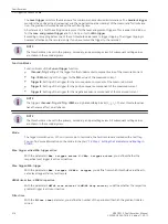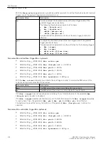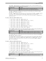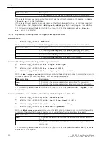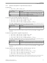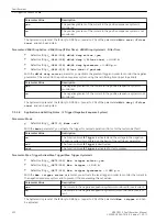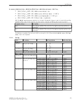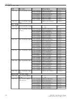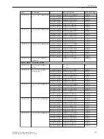
Gradient Trigger for Rising and Dropping Gradients of the Current
With the parameters
dM/dt rise (/Filter time)
and
dM/dt drop (/Filter time)
, you define
from which threshold value the parameterized filtering time starts a fault record.
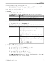
Application and Setting Notes I Fund. Trig
Parameter: Mode
•
Default setting
(_:9751:1) Mode
=
off
With the
Mode
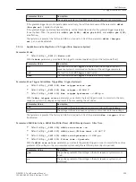
parameter, you activate the trigger for normal operation (On) or for the test mode (Test).
Parameter Value
Description
on
The function block
Trig. I fund 1
is activated and the fundamental
component monitored according to the set trigger parameters.
off
The function block
Trig. I fund 1
is deactivated.
test
The function block
Trig. I fund 1
is activated for test purposes.
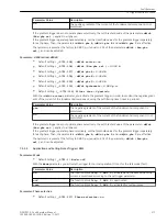
Parameter: Phase-selective
•
Default setting
(_:9751:117) Phase-selective
=
no
With the
Phase-selective
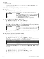
parameter, you define whether you want to set the threshold values of the level
triggers and of the gradient trigger phase-selectively or not.
Parameter Value
Description
no
You do not adjust the threshold values of the level triggers and of the
gradient trigger phase-selectively.
The following threshold values apply to all 3 phases:
•
Max. (Non-phs sel.)
•
Min. (Non-phs sel.)
•
+dM/dt (Non-phs sel.)
•
-dM/dt (Non-phs sel.)
The phase-selective parameters can be set for each trigger, but are not
effective
yes
You adjust the threshold values of the level triggers and of the gradient
trigger phase-selectively.
The phase-selective parameters are then effective for the following triggers:
•
Max. trigger
•
Min. trigger
•
dM/dt rise (/Filter time)
•
dM/dt drop (/Filter time)
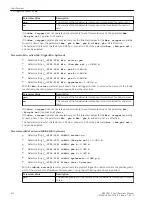
Parameter: Max. active/Max. Trigger/Max. hysteresis
•
Default setting
(_:9751:101) Max. active
=
yes
•
Default setting
(_:9751:105) Max. (Non-phs sel.)
=
1.200 A
•
Default setting
(_:9751:118) Max. phs A
=
1.200 A
•
Default setting
(_:9751:119) Max. phs B
=
1.200 A
•
Default setting
(_:9751:120) Max. phs C
=
1.200 A
•
Default setting
(_:9751:113) Max. hysteresis
=
0.980 p.u.
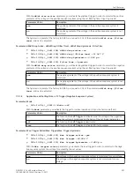
With the
Max. active
parameter, you activate the level trigger in order to monitor the current of the funda-
mental component and prevent it from exceeding the set values.
7.5.2.4
Fault Recorder
7.5 Trigger Functions 3-Phase
SIPROTEC 5, Fault Recorder, Manual
315
C53000-G5040-C018-5, Edition 11.2017
Summary of Contents for SIPROTEC 5
Page 8: ...8 SIPROTEC 5 Fault Recorder Manual C53000 G5040 C018 5 Edition 11 2017 ...
Page 18: ...18 SIPROTEC 5 Fault Recorder Manual C53000 G5040 C018 5 Edition 11 2017 ...
Page 134: ...134 SIPROTEC 5 Fault Recorder Manual C53000 G5040 C018 5 Edition 11 2017 ...
Page 212: ...212 SIPROTEC 5 Fault Recorder Manual C53000 G5040 C018 5 Edition 11 2017 ...
Page 422: ...422 SIPROTEC 5 Fault Recorder Manual C53000 G5040 C018 5 Edition 11 2017 ...
Page 426: ...426 SIPROTEC 5 Fault Recorder Manual C53000 G5040 C018 5 Edition 11 2017 ...
Page 452: ...452 SIPROTEC 5 Fault Recorder Manual C53000 G5040 C018 5 Edition 11 2017 ...
Page 490: ...490 SIPROTEC 5 Fault Recorder Manual C53000 G5040 C018 5 Edition 11 2017 ...

