


Operator Functions
Vision Sensor VS 130
A5E00199459-01
5-3
5.2.3 "Info"
Menu
With the "Info" menu, you obtain information on the following:
•
the part of the learned code with which the read code will be compared
•
the absolute and relative number of successful read operations
•
the absolute and relative number of unsuccessful read operations
•
the absolute and relative number of read operations with a positive comparison
result
•
the evaluation time required for the code currently being read
•
the relative number of read operations, for which the time available for
evaluation was not adequate
Step
Display
Activity
1
Code
STOP
> Info
ESC OK
At the "RUN" menu level on the processing unit, select "Info" with the
arrow buttons
▼
and
▲
and press "OK". This opens the first
information screen form.
2
C 02 MATCH
Off
1/6
↓
OK
You can display further information with the arrow buttons
▲
and
▼
By pressing "OK", you returned to the highest hierarchy level of the
"RUN" menu level.
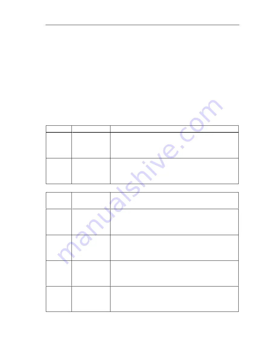
Information
Form
No.
Display
Description
1
C 02 MATCH
Off
1/6
↓
OK
The value "Off" was set for the Match-Opt parameter of code 2, in
other words, there is no comparison of the codes read.
1
C 02 MATCH
All
=This can..
1/6
←↓→
OK
The value "All" was set for the Match-Opt parameter of code 2, in
other words, the read codes will be compared with the entire learned
code.
1
C 02 MATCH
Pos=6..8
=can
←
1/6
←↓→
OK
The value "Position" was set for the Match-Opt parameter of code 2,
in other words, The read codes are checked to see whether they
contain the string "can" at position 6 to 8.
1
C 02 MATCH
ID=T
=his can ..
1/6
←↓→
OK
The value "ID" was set for the Match-Opt parameter of code 2, in
other words,
MATCH-ID has the value "T" and the substring begins with "his can "
(the other characters are no longer visible in the display field).


