Index-3
S7-200 Programmable Controller, CPU 210
C79000-G7076-C235-01
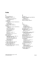
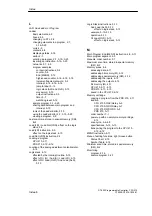
Creating a program, 2-7–2-9, 3-1–3-25
creating a project, 2-6
interrupt routine, 4-14
high-speed counter example, 4-14–4-16,
5-16
Creating networks, 2-7, 2-8
Current value
counters, 5-8
current value saved at power down, 2-12
timers, 5-6
Cut, copy, and paste
in a Status Chart, 2-15
in a Symbol Table, 2-14
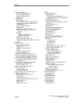
D
Data checking, not supported, 4-13
Data sheets
CPU 210 AC/AC/Relay, A-8
CPU 210 AC/DC/Relay, A-6
CPU 210 DC/DC/DC, A-4
DC input simulator, A-15
memory cartridge, A-12, A-13
PC/PPI cable, A-14
PDS 210, A-10
Data typing, not supported, 4-13
DC input simulator
order number, F-1
specifications, A-15
DC installation, guidelines, 1-10
DC relay, 1-12
DC transistor, protecting, 1-12
Debugging the program, 2-16
scan cycle, 4-8
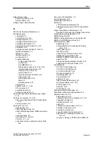
Decrement Word (DECW) instructions, 5-9
example, 5-9
Deleting and inserting rows
in a Status Chart, 2-15
in a Symbol Table, 2-14
Designing control logic, example with a sample
application, 3-4–3-8
Device number, timers and counters, 4-12
Digital inputs
addressing, 4-11–4-13
reading, 4-6–4-9
Digital outputs
addressing, 4-11–4-13
writing to, 4-6–4-9
Dimensions
CPU 210, 1-5
DIN rail, 1-5
PDS 210, 1-5
DIN rail
dimensions, 1-5
installing on a, 1-6
using DIN rail stops, 1-6
Disable Interrupt (DISI) instruction, 5-14–5-17
disabling and enabling interrupts, 5-14
Displaying status in ladder, 2-16
Downloading a program
CPU 210, 2-11
PDS 210, 2-10–2-12
sample program, 3-23
Duplicate symbol names, 2-13
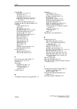
E
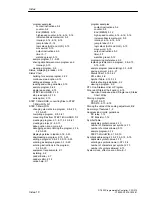
ED (Negative Transition) instruction, 5-3
Editing a cell in a Status Chart, 2-15
Editing a cell in the Symbol Table, 2-14
Editing a program, 3-15–3-20
Editing functions, using right mouse button
Status Chart, 2-15
Symbol Table, 2-14
Editing tools
Status Chart, 2-15
Symbol Table, 2-14
Electromagnetic specifications, A-3
Elements of an address, 4-11
Elements of an STL instruction, 4-10
Enable Interrupt (ENI) instruction, 5-14–5-17
enabling and disabling interrupts, 5-14
Enclosure
See also Panel box
clearance requirements, 1-4
installing in a panel box, 1-7
End instruction, 5-11
Ending the main program segment, 4-5, 5-11
Entering a program
in ladder, 3-15–3-20
in STL, 3-15
Entering a symbolic name in STL, 2-8
Entering comments, in STL, 2-8, 3-15
Entering symbols, 2-13–2-15
Entries
duplicate symbol names, 2-13
number of characters per symbol, 2-13
number of symbols allowed in a Symbol
Table, 2-13
Environmental specifications, A-2
Equipment requirements, 1-2
STEP 7-Micro/WIN, 2-1
Error codes
compile rule violations, C-1
error handling for the CPU 210, C-2
fatal errors, C-1
Index
Summary of Contents for Simatic S7-200 CPU 210
Page 10: ...x S7 200 Programmable Controller CPU 210 C79000 G7076 C235 01 Contents ...
Page 116: ...A 16 S7 200 Programmable Controller CPU 210 C79000 G7076 C235 01 CPU 210 Data Sheets ...
Page 126: ...F 2 S7 200 Programmable Controller CPU 210 C79000 G7076 C235 01 CPU 210 Order Numbers ...
Page 138: ...Index 12 S7 200 Programmable Controller CPU 210 C79000 G7076 C235 01 Index ...


