4-2
S7-200 Programmable Controller, CPU 210
C79000-G7076-C235-01
4.1
Guidelines for Designing a Micro PLC System
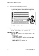
There are many methods for designing a Micro PLC system. This section provides some
general guidelines that can apply to many design projects. Of course, you must follow the
directives of your own company’s procedures and of the accepted practices of your own
training and location. Figure 4-1 shows some of the basic steps in the design process.
Partition your process or machine.
Create the functional specifications of the units.
Specify the operator stations.
Create the PLC configuration drawings.
Create a list of symbolic signal-naming conventions (optional).
Design the hard-wired safety circuits.
Figure 4-1
Basic Steps for Planning a PLC System
Partitioning Your Process or Machine
Divide your process or machine into sections that have a level of independence from each
other. These partitions will determine the boundaries between controllers and will influence
the functional description specifications and the assignment of resources.
Creating the Functional Specifications
Write the descriptions of operation for each section of the process or machine. Include the
following topics:
S
Input/output (I/O) points
S
Functional description of the operation
S
Permissives (states that must be achieved before allowing action) for each actuator
(solenoids, motors, drives, etc.)
S
Description of the operator interface
S
Interfaces with other sections of the process or machine
Basic Concepts for Programming the CPU 210
Summary of Contents for Simatic S7-200 CPU 210
Page 10: ...x S7 200 Programmable Controller CPU 210 C79000 G7076 C235 01 Contents ...
Page 116: ...A 16 S7 200 Programmable Controller CPU 210 C79000 G7076 C235 01 CPU 210 Data Sheets ...
Page 126: ...F 2 S7 200 Programmable Controller CPU 210 C79000 G7076 C235 01 CPU 210 Order Numbers ...
Page 138: ...Index 12 S7 200 Programmable Controller CPU 210 C79000 G7076 C235 01 Index ...


