S5-95U, Second Serial Interface
Computer Link with 3964(R) Transmission Protocol
3.3
Coordination Bytes for a Computer Link
The computer link monitors data traffic and writes status and error messages in two different bytes,
the
”
send
”
(KBS) and
”
receive
”
(KBE) coordination bytes.
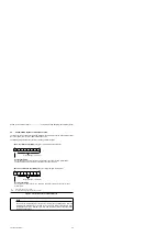
The following diagram shows the structure of the two coordination bytes.
Figure 3-6 Structure of the Coordination Bytes
”
Send
”
coordination byte (KBS) (flag byte or high-order byte in data word)
Sending permitted
Set by the user and reset by the computer link when the send procedure is terminated.
The send procedure is activated by a positive-going edge at this bit.
Error message ( Table 3-1)
2
7
2
0
R
R
R
R
R
R
W/R
R
”
Receive
”
coordination byte (KBE) (flag byte or high-order byte in data word)
Receiving permitted
Set by the user and reset by the computer link after receiving data either with or
without errors.
Error message ( Table 3-2)
R:
Read Only (bit may only be read)
W/R:
Write / Read (bit may be both read and overwritten)
2
7
2
0
R
R
R
R
R
R
W/R
R
Note
The bits in the coordination bytes can be set or reset by the operating system after any
instruction and independently of the PLC cycle. This means that multiple scanning of the
coordination bit within a program cycle may lead to different results. (Important when
evaluating pulse edges!)
EWA 4NEB 812 6095-02
3-7


