ASCII Driver
S5-95U, Second Serial Interface
4.3
Coordination Bytes for Use of the ASCII Driver
The ASCII driver monitors data traffic and stores status and error messages in two bytes, the
”
send
”
(KBS) and
”
receive
”
(KBE) coordination bytes.
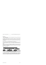
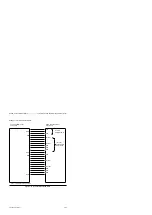
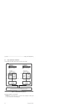
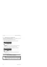
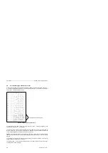
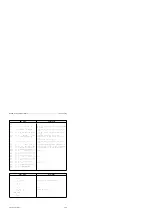
The following display shows the structure of the two coordination bytes.
Figure 4-6 Structure of the Coordination Bytes
”
Send
”
coordination byte (KBS) (flag byte or high-order byte in the data word)
Sending allowed
Is set by the user and reset by the ASCII driver when the send procedure in
terminated.
If a positive-going edge occurs in this bit, the send procedure is activated.
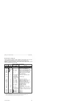
Error message ( Table 4-1)
2
7
2
0
R
R
R
R
R
R
W/R
R
”
Receive
”
coordination byte (KBE) (flag byte or high-order byte in the data word)
Receiving allowed
Is set by the user and reset by the ASCII driver after receiving with or without errors.
Error message ( Table 4-1)
R:
Read Only (bit may only be read)
W/R:
Write / Read (bit may be read and overwritten)
2
7
2
0
R
R
R
R
R
R
W/R
R
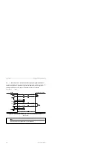
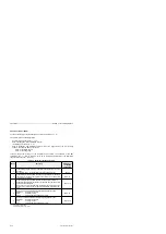
Note
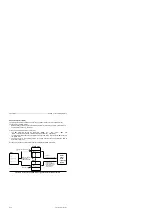
The bits in the coordination bytes can be set and/or reset by the operating system after
every instruction irrespective of the PLC scan cycle. That is, a repeated scan of a
coordination bit in a program cycle can lead to different results. (Caution during pulse
edge evaluation!)
4-6
EWA 4NEB 812 6095-02

