ASCII Driver
S5-95U, Second Serial Interface
4.2
Data Traffic with the ASCII Driver
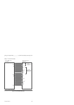
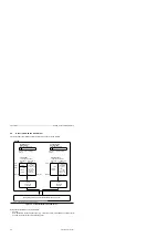
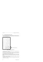
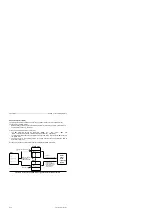
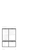
Figure 4-5 shows the principle of operation of the ASCII driver in schematic form.
Figure 4-5 Functional Model of the ASCII Driver
Number of
net data *
Byte 3
.
.
.
.
Byte 1026
Byte 1
Byte 2
1 ... 1024
bytes of
net data
Internal
output buffer
(1024 bytes)
Byte 1
.
.
.
.
.
.
.
Internal
input buffer
(1024 bytes)
Communication partner
Third-partny device which is able to handle the ASCII driver
*
Byte 1
ˆ
-
High-order part; Byte 2
ˆ
-
Low-order part
Byte 1024
Byte 1024
Error messages
Error messages
S5-95U
Coordination byte
Sending (KBS)
(in the flag or data area)
Sending
allowed
Send mailbox
(in the flag or data area)
a a a a
a a a a
a a a a
a a a a
a a a a
Receiving
allowed
Coordination byte
Receiving (KBE)
(in the flag or data area)
a a a a
a a a a
a a a a
a a a a
a a a a
Receive mailbox
(in the flag or data area)
in mode 2, 3,
4, 5 or 6:
in mode 1, 7
or 8:
in mode 2, 3,
4, 5 or 6:
in mode 1, 7
or 8:
1...1022 bytes
of net data +
2 bytesend-of-
text or 1 to
1023 bytes of
net data+1
byte end-of-
text
1 ... 1024
bytes of
net data
1...1022 bytes
of net data +
2 bytes end-
of-text
or 1...1023
bytes of net
data +1 byte
end-of-text
Data traffic is possible in one or two directions:
•
Sending
Data available in the send mailbox (SF) (e.g. contents of a DB) are buffered in an output buffer
and from there sent to the communication partner.
4-4
EWA 4NEB 812 6095-02


