I
Second
Interface
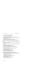
Description of the System
1.3
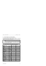
Configuration of the PLC
and
Assignment
of the Second Serial
Interface
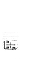
The figure below shows all displays, controls and interfaces of the
(6ES5095-8MC01).
5
DIGITAL
0,6A
L+
❑
n
❑
O 0 2
.1
❑
o @ 3
. 2 a
❑
n
.3
❑
n
. 4 a
❑
n @ 6
7 @
❑
o
❑
o
8A
9 @
❑
n
OFFI
LOW
M
lo@
❑
010
❑
o
12@
❑
@12 3).0
13@
❑
@
1 3
14@
❑ ❑
@14 @.2
.6 18@
❑
@18 .6
.7 19@
❑
@19
M
0
❑
0 0
0231
D
0
0
0
0
0
0
0
0
0
0
0
0
0
RUN
0
0
0
0
0
STOP
0
0
8X
lx
lx
C 24V
o
o
0
0
0
0
0
0
0
0
7
-
o
8
-
o
9
- - o
10
-
o
11
- - o
12
2
3
4
5
6
7
8
Battery compartment
Front connector
for digital inputs (1 32.0 . . . I 33.7) and
for digital outputs (Q 32.0 . . . Q 33.7)
Battery low LED
On/off switch
LEDs for digital inputs and outputs
Terminals for connecting the power supply
Cable connector for S5-1OO modules
Interface for analog inputs (IW 40 . . .
54) and
for analog outputs (QW 40)
Second serial interface
RUN/STOP LEDs: green LED
RUN; red LED STOP
RUN/STOP/COPY SWITCH
Receptacle for user
Interface for PG, PC, OP or
L1 LAN
Interface for interrupt inputs (1 34.0 . . . 34.3) and
for counter inputs (IW 36,
38)
Figure 1-2
LEDs, Controls and Interfaces
4NEB 8126095-02
1-7

