background image


MP 377 15" Touch daylight readable 
A5E02341631-03, 06/2009 

11


Mounting the HMI device 

Requirement 
These are the requirements: 


All packaging components and protective foils should be removed from the HMI device. 


The HMI device comes equipped with a mounting seal. 


10 mounting clamps from the accessory kit 


The mounting cut-out is burr-free. 

To ensure the necessary degree of protection on the front of the HMI device, you will have to observe the mounting clamp 

positions listed below. 

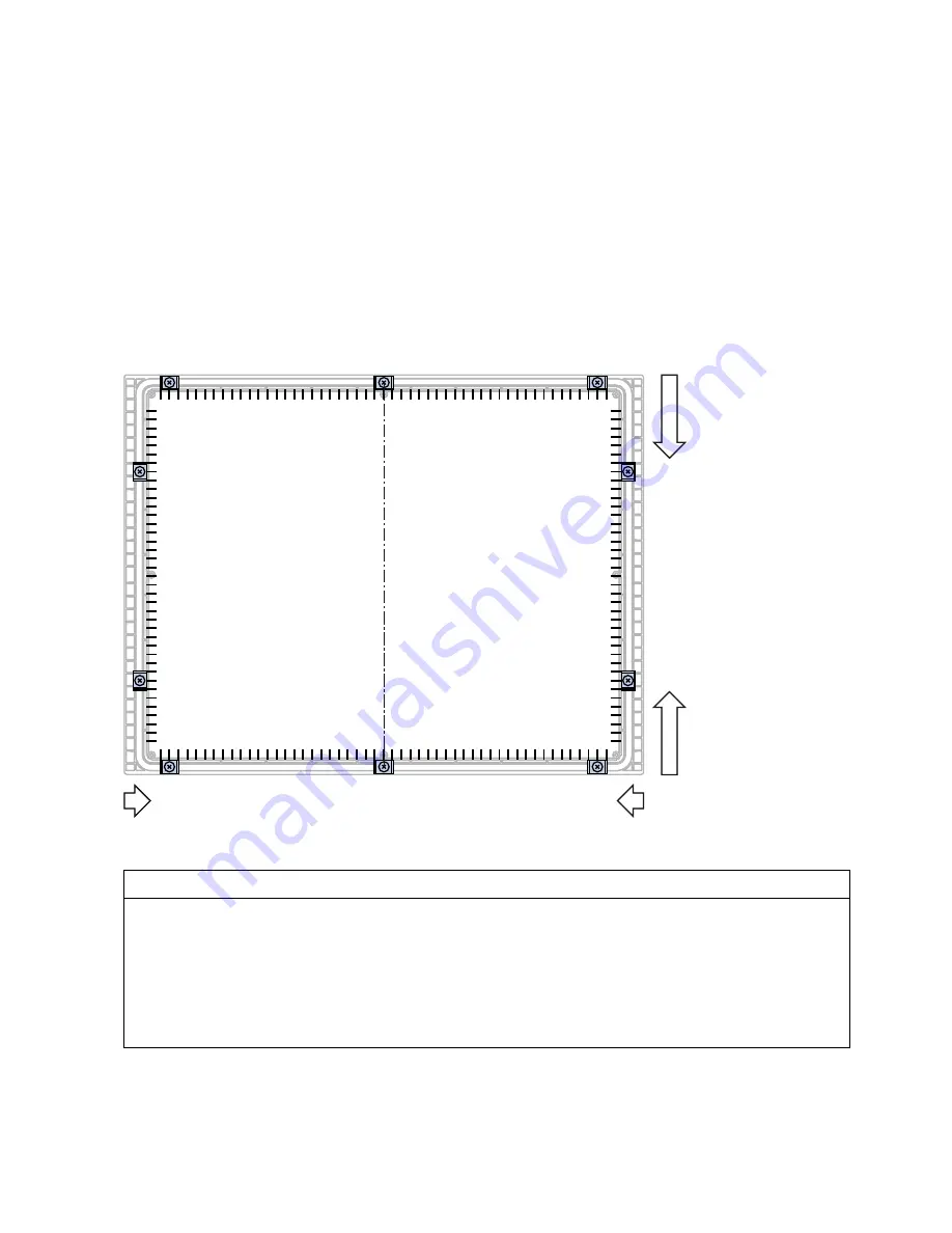
Position of the mounting clamps 
The following figure shows the positions for installation of the mounting clamps.  


Procedure    


CAUTION 
Degree of protection on front at risk 
If the mounting seal is damaged, if it does not fully rest in the groove for the mounting seal or if the ends of the mounting 

seal do not meet in the groove, then the degree of protection is not guaranteed for the front of the HMI device. 
Check the mounting seal and its proper seat. 
Damage due to overheating 
If the vents are covered on the HMI device or if the air does not flow freely to the fans, the HMI device may be damaged. 

The approvals and warranties for the HMI device will become void. 
Ensure unblocked ventilation of the HMI device. 


Summary of Contents for Simatic MP 377

Page 1: ...onnecting the HMI device 4 Operator controls 5 Configuring the operating system 6 Service and maintenance 7 Technical specifications 8 Appendix A Abbreviations B SIMATIC HMI HMI device MP 377 15 Touch daylight readable WinCC flexible Operating Instructions Compact 04 2009 A5E02532357 01 The following supplement is part of this documentation No Designation Drawing number Edition 1 Product Informati...

Page 2: ... only be performed by qualified personnel Within the context of the safety notes in this documentation qualified persons are defined as persons who are authorized to commission ground and label devices systems and circuits in accordance with established safety practices and standards Proper use of Siemens products Note the following WARNING Siemens products may only be used for the applications de...

Page 3: ...onnel Operators Maintenance personnel Read especially the information in the section Safety instructions Required knowledge General knowledge in the field of automation engineering is required to understand this manual Scope of the manual This manual applies to the MP 377 15 Touch daylight readable HMI device order number 6AV6644 8AB20 0AA0 Note This manual is an amendment to the operating instruc...

Page 4: ...P Keyboard operation Please observe notes labeled as follows Note A note contains important information about the product and its use or a specific section of the manual to which you should pay particular attention Naming conventions The following naming conventions apply Term This also applies to Control cabinet Mounting cabinet Enclosure Console Switchboard Plant Machining centers Machines Syste...

Page 5: ...echnical Support http support automation siemens com Online support request form http www siemens com automation support request Service http www siemens com automation service Recycling and disposal The HMI devices described in these operating instructions can be recycled due to the low levels of pollutants Contact a certified disposal service company for environmentally sound recycling and dispo...

Page 6: ...Preface MP 377 15 Touch daylight readable WinCC flexible 6 Operating Instructions Compact 04 2009 A5E02532357 01 ...

Page 7: ...5 3 1 General information 25 3 2 Mounting positions and type of fixation 25 3 3 Preparation for mounting 26 4 Mounting and connecting the HMI device 29 4 1 Mounting the HMI device 29 4 2 Connecting the HMI device 31 4 2 1 Overview 31 4 2 2 Connecting the Fan 33 4 2 3 Connecting the power supply 33 4 2 4 Switching on and testing the HMI device 35 5 Operator controls 37 5 1 Front operator controls 3...

Page 8: ...1 Maintenance and Care 51 7 2 Repair 52 8 Technical specifications 53 8 1 Dimension drawing 53 8 2 Technical Specifications 54 8 3 Ambient conditions 56 8 4 Transport and Storage Conditions 57 A Appendix 59 A 1 ESD guideline 59 A 2 Configure SetBrightness function 61 A 2 1 Overview 61 A 2 2 Add on SetBrightness 62 B Abbreviations 65 Glossary 67 Index 69 ...

Page 9: ...gs and in control stations onboard ships You can operate the HMI device outdoors if it is installed in a suitable control cabinet The necessary extended ambient temperature range during operation can be created with the help of active heating and cooling in the control cabinet We recommend that you consult an experienced control cabinet designer for appropriate sizing Intelligent control of heatin...

Page 10: ...t readable display with LED backlighting High brightness up to 560 cd m Energy saving LED backlighting dimming range from 0 to 100 High contrast up to 700 1 Suitable for daylight applications The transflective technology combines the advantages of reflective and transmissive displays The reflective properties of the display offer good readibility even in direct sunlight The transmissive component ...

Page 11: ...frame Front membrane Display touch screen Protection for memory cards Oblong holes for mounting clamps air vents Fans Fixing element for strain relief The term front operating panel as used in this manual corresponds to the front view with operating elements Bottom view Mains terminal for power supply of HMI device Interfaces Mains terminal for power supply of fans Fans ...

Page 12: ...aylight readable WinCC flexible 12 Operating Instructions Compact 04 2009 A5E02532357 01 Rear view Rating plate Protection for memory cards Mounting seal DIP switch Mains terminal for power supply of fans Fixing elements for strain relief ...

Page 13: ...g content Mounting clamps for mounting the HMI device One mains terminal for power supply of HMI device One mains terminal for power supply of fans One product information Installing HMI device 1 4 Service pack A service pack is available for the MP 377 15 daylight readable The service pack includes the following components A mounting seal A pouch with the following content Mounting clamps for mou...

Page 14: ...Overview 1 4 Service pack MP 377 15 Touch daylight readable WinCC flexible 14 Operating Instructions Compact 04 2009 A5E02532357 01 ...

Page 15: ...afety notes Working on the control cabinet WARNING Open Equipment The HMI device is an open equipment This means that the HMI device may only be installed in a control cabinet whereby the device can be operated from the front panel Access to the control cabinet in which the HMI device is installed should only be possible by means of a key or tool and only for trained and authorized personnel Dange...

Page 16: ...0079 0 EN 60079 15 EN 61241 0 EN 61241 1 the following approvals are in place II 3 G Ex nA II Tx II 3 D Ex tD A22 IP6X T xx C x Temperature values see design examination certificate The design examination certificate is available at the following Internet address http support automation siemens com CE approval The HMI device meets the general and safety related requirements of the following EC dir...

Page 17: ... UL approval Underwriters Laboratories Inc to UL 508 Industrial Control Equipment CSA C22 2 No 142 Process Control Equipment or Underwriters Laboratories Inc to UL 508 Industrial Control Equipment CSA C22 2 No 142 Process Control Equipment UL 1604 Hazardous Location CSA 213 Hazardous Location Approved for use in Class I Division 2 Group A B C D Tx Class I Zone 2 Group IIC Tx or non hazardous locat...

Page 18: ...lass A IEC 61131 The HMI device meets the requirements and criteria conforming to IEC 61131 2 Programmable Logic Controllers Part 2 equipment requirements and testing Requesting certificates Copies of the certificates and reports can be requested from the following address Siemens AG Industry Sector I IA AS R D ST PO Box 1963 92209 Amberg Germany Certificates are also available at the following In...

Page 19: ...mit Class B conforming to EN 55011 for RF interference Suitable measures for achieving the required RF interference level for Limit Class B include for example Installation of the HMI device in a grounded control cabinet Use of filters in electrical supply lines Individual acceptance is required Operation in potentially explosive atmosphere zone 2 and 22 DANGER Degree of hazard There is an explosi...

Page 20: ...connecting any connectors Potentially explosive atmosphere zones 2 and 22 Areas subject to explosion hazard are divided into zones The zones are differentiated according to the probability of the existence of an explosive atmosphere Zone Degree of hazard Example 2 Explosive gaseous atmosphere occurs only seldom and for a short period Areas around flanged pipe joints with flat gaskets in closed roo...

Page 21: ...e see design examination certificate Refer to the operating instructions for details of limitations resulting from the ambient temperature range In situations where the temperature on the cable at the cable inlet of the control cabinet exceeds a temperature of 70 C or where the temperature on the wire branching point exceeds 80 C under operating conditions the temperature specifications of the cab...

Page 22: ...d the PROFIBUS Networks manual also apply for the installation of the HMI device Pulse shaped Interference The table below shows the electromagnetic compatibility of modules in relation to pulse shaped interference This requires the HMI device to meet the specifications and directives for electrical installation Pulse shaped interference Tested with Corresponds to severity Electrostatic discharge ...

Page 23: ...etic fields according to IEC 61000 4 3 80 amplitude modulation at 1 kHz with 10 V m in the range of 80 MHz to 1 GHz with 3 V m in the range 1 4 GHz to 2 GHz with 1 V m the range 2 GHz to 2 7 GHz 10 V m with 50 pulse modulation at 900 MHz 10 V m with 50 pulse modulation at 1 89 GHz 3 HF interference current on cables and cable shielding conforming to IEC 61000 4 6 Test voltage 10 V at 80 amplitude ...

Page 24: ...Safety instructions and approvals 2 5 Electro Magnetic Compatibility MP 377 15 Touch daylight readable WinCC flexible 24 Operating Instructions Compact 04 2009 A5E02532357 01 ...

Page 25: ...ntal mounting The HMI device can be installed as follows Vertical Inclined at an angle between 0 and 90 Horizontal Temperature Extension Kit The Temperature Extension Kit lets you use the HMI device relatively independent of the actual ambient conditions You accomplish this feat because the Temperature Extension Kit creates an environment in the cabinet that is within the limits permitted for oper...

Page 26: ...o the information in the chapter Technical Specifications Page 54 can only be ensured if the HMI device is installed with the supplied mounting clamps Additional fastening bore holes or threaded bolts are not required for the mounting cutout The front material has to consist of sheet steel or material of a strength that corresponds to at least the stability of sheet steel Mounting cutout The follo...

Page 27: ...earances Where Clearance Observe a clearance above and below the mounting cutout for ventilation of 50 mm Right and left of the mounting cut out for the mounting clamps 18 mm At the rear in addition to the mounting depth of the HMI device at least 10 mm Note Ensure that the maximum ambient temperature is not exceeded when mounting the device in a control cabinet You can install the option TEK Temp...

Page 28: ...Planning application 3 3 Preparation for mounting MP 377 15 Touch daylight readable WinCC flexible 28 Operating Instructions Compact 04 2009 A5E02532357 01 ...

Page 29: ...protective foils should be removed from the HMI device The HMI device comes equipped with a mounting seal 10 mounting clamps from the accessory kit The mounting cut out is burr free To ensure the necessary degree of protection on the front of the HMI device you will have to observe the mounting clamp positions listed below Position of the mounting clamps The following figure shows the positions fo...

Page 30: ... for the HMI device will become void Ensure unblocked ventilation of the HMI device Note Always mount the HMI device according to the instructions in this manual Tighten the threaded pins of the mounting clamps until the HMI device is flush with the front of the control cabinet You have the option to tighten the mounting clamps with a maximum torque of 0 2 Nm Proceed as follows 1 Check the mountin...

Page 31: ...he connection sequence for the HMI device Connect the HMI device in the following sequence 1 Equipotential bonding 2 Connecting the power supply of the fans 3 Connecting the power supply of the HMI device 4 PLC 5 Configuring PC as necessary Disconnect the HMI device from the terminals in reverse order of connection NOTICE Do not switch on the HMI device in case of condensation Humidity can show up...

Page 32: ... HMI device RS 422 RS 485 port X10 IF 1B PROFINET ports X1 P1 and X1 P2 USB ports X20 and X21 Line in and micro Line out You connect the PROFIBUS DP or MPI to the X10 IF 1B interface Connecting the cables When connecting the cables ensure that the contact pins are not bent Secure the connectors with screws Use cable ties to secure the cables at the fixing element for strain relief The following il...

Page 33: ...ption of the connection sequence refer to chapter Overview Page 31 Please note the Maintenance and Care Page 51 chapter 4 2 3 Connecting the power supply Configuration graphic The following figure shows the connection between the power supply and HMI device Reverse polarity protection The HMI device is equipped with a reverse polarity protection circuit This protection does not apply to the connec...

Page 34: ...s select a central point of termination Requirement These are the requirements The HMI device is assembled 2 connection terminals The connection terminals are included in the accessory kit and are designed for cables with a cross section of 1 5 mm2 Procedure Proceed as follows NOTICE Damage possible If the mains terminal is plugged into the HMI device and the cable is connected then pressure on th...

Page 35: ...abel of the sockets on the rear of the HMI device 1 9 2 Plug in the mains terminal for the power supply of the HMI device into the socket 3 Connect the mains terminal for the power supply of the fans 4 Plug in the mains terminal into the socket 4 2 4 Switching on and testing the HMI device Conduct a power up test according to the operating instructions MP 377 WinCC flexible chapter Turning on and ...

Page 36: ...Mounting and connecting the HMI device 4 2 Connecting the HMI device MP 377 15 Touch daylight readable WinCC flexible 36 Operating Instructions Compact 04 2009 A5E02532357 01 ...

Page 37: ... operate The comprehensive dimming range with 256 settings makes for fatigue free reading in very bright and very dark ambient lighting Note Please observe the notes on the touch screen in the operating instructions MP 377 You operate the touch screen as follows Touching it directly with a finger Touching it with a finger protected by a thin glove You cannot operate the touch screen with other dev...

Page 38: ...talled memory cards are secured and protected in their slots by a slot cover Note Please observe the notes on the memory card in the operating instructions MP 377 Procedure Proceed as follows 1 Remove the screw in the slot cover 2 Remove the slot cover from the HMI device rear panel 3 Install a memory card or remove it from the slot 4 Insert the slot cover into the slots 5 Tighten the screw in the...

Page 39: ...ction of the same name in the operating instructions listed above 6 2 Calibrating the touch screen Introduction Depending on the mounting position and viewing angle it is possible that parallax may occur when operating the touch screen To prevent any resulting operating errors you may need to calibrate the touch screen during the startup phase or while in runtime Nine calibration crosshairs are di...

Page 40: ...e calibration crosshairs and the buttons one after the other in 5 s intervals Otherwise the OP Properties dialog will be displayed again Proceed as follows 1 Click on the Recalibrate button The following dialog opens HYLFH RQ KROH HVNWRS 2 Briefly touch the middle of the calibration crosshairs Confirm the calibration with a green check mark at this location the next calibration crosshairs will be ...

Page 41: ... 04 2009 A5E02532357 01 41 3 Touch the Confirm button 3OHDVH SUHVV WKH EXWWRQ WR FRQILUP FDOLEUDWLRQ RQILUP The calibration is saved The OP Properties dialog Touch tab is displayed again If you do not touch the Confirm button within 5 s your original calibration will be retained 4 Close the dialog Result The HMI device touch screen is calibrated ...

Page 42: ...by the eye as linear You change the brightness as follows Single stage by using a button Multi stage by using the slider control You can limit the number of brightness settings You can also enter a value for the brightness with which the HMI device is to start You can change the brightness of the display during the startup phase or while in runtime Pay particular attention to the section Configure...

Page 43: ... Button for entry of value for maximum display brightness Value for maximum display brightness Slider control Button for increase in brightness Increment increase brightness by one increment Currently selected brightness Saved brightness Button for setting currently selected brightness Button for decrease in brightness Increment decrease brightness by one increment Button for entry of value for mi...

Page 44: ...while you are operating these buttons The change in the group Current Brightness will be displayed with the currently selected brightness Note If you enter a value for Max Brightness that is smaller than the saved brightness value the message Max Cur will be displayed Select a smaller value or operate the Set Current button It is then possible to accept the altered value 3 Click on the Set Max but...

Page 45: ...e last saved value after 25 seconds You can set any value between the saved brightness value and 0 Note If you enter a value for Min Brightness that is smaller than the saved brightness value the message Min Cur will be displayed Select a smaller value or operate the Set Cur button It is then possible to accept the altered value 7 Click on the Set Min button 8 Click on the Apply button The followi...

Page 46: ...screen The function associated to the key or button will not be executed by this NOTICE Turning off backlighting The brightness of the backlighting decreases incrementally during its operational life You will increase the service life of the display considerably by turning off backlighting rather than by reducing backlighting or using a screen saver Activating the screen saver Screen contents may ...

Page 47: ... the interval in minutes after which the backlighting is to be turned off Entering 0 will deactivate option for turning off backlighting 2 Enter the number of minutes before the screen saver is to be activated The minimum time is 5 minutes and the maximum time is 71582 minutes Entering 0 disables the screen saver 3 Select either the screen saver or an empty screen If you want the screen saver to f...

Page 48: ...n the following cases You have activated or deactivated the PROFINET IO direct keys You have changed the time zone setting You have changed the automatic daylight savings and standard setting NOTICE Data loss when the HMI device is restarted All volatile data is lost when the HMI device is restarted Check the following The project on the HMI device is complete No data is being written to the flash...

Page 49: ...restarting Button for restart Button for reset to factory settings and subsequent restart 2 If you want to restart the HMI device press the Reboot button The HMI device restarts without delay 3 If you want to reset the HMI device to the factory settings and then restart press the Prepare for Reset button You are given the option of resetting the HMI device to the factory settings through ProSave T...

Page 50: ...Configuring the operating system 6 5 Restarting the HMI device MP 377 15 Touch daylight readable WinCC flexible 50 Operating Instructions Compact 04 2009 A5E02532357 01 ...

Page 51: ...e Display Housing frame front membrane and display have different resistance levels to chemical and mechanical influences General information on cleaning NOTICE Damage to the front operating panel possible You can damage the front operating panel if you clean the display with aggressive solvent containing greasing or abrasive detergents acids or caustic solutions scratching cleaning rags or equipm...

Page 52: ... water jet contacts the screen Proceed as follows 1 Switch off the HMI device When the system provides such an operator control you can also activate a clean screen on the touch screen during operation 2 Apply the cleansing agent to the front operating panel 3 Clean the front operating panel with a window wiper or cloth 4 Wipe off the edges of the front operating panel 7 2 Repair If the unit needs...

Page 53: ...MP 377 15 Touch daylight readable WinCC flexible Operating Instructions Compact 04 2009 A5E02532357 01 53 Technical specifications 8 8 1 Dimension drawing OO GLPHQVLRQV LQ PP ...

Page 54: ...s 3 mm Hardness to Mohs 7 Colors displayable 16 million Backlighting Half brightness lifetime typical LED 50 000 h Display area active 304 1 mm x 228 1 mm 15 Resolution 1024 x 768 pixels Dimming range 256 increments from 0 to 560 cd m2 The brightness values are recommended values Dimming range limitable Yes Contrast 700 1 typically 480 1 minimum Response time 20 ms Input unit Type Touchscreen proj...

Page 55: ...aximum permissible 35 V 500 ms Time between two transients minimum 50 s Fuse internal Electronic Current consumption Typical Constant current maximum Power on current surge I2t approx 1 500 mA Approx 2 800 mA Approx 5 0 A2s Supply connection fan Rated voltage Valid range 24 VDC 19 2 V to 28 8 V 20 20 Current consumption Constant current typical Inrush current For the two fans in sum Approx 50 mA A...

Page 56: ...utually vertical axes Shock IEC 60068 Part 2 29 15 g peak value 11 ms duration Shock type Half sine shock direction in each of the three mutually vertical axes always with 3 shocks in direction Climatic ambient conditions The following table shows the climatic conditions for operation of the HMI device Ambient conditions Permitted range Remarks Temperature 0 to 50 C Temperature shock 0 to 50 C cyc...

Page 57: ...imatic conditions comply to the following standards IEC 60721 3 3 Class 3K7 for storage IEC 60721 3 2 Class 2K4 for transport Mechanical transport and storage conditions The mechanical conditions correspond to IEC 60721 3 2 Class 2M2 Type of condition Permitted range Drop test in transport package 1 m Temperature 40 to 80 C Atmospheric pressure 1 140 hPa to 660 hPa corresponds to an elevation of 1...

Page 58: ...Technical specifications 8 4 Transport and Storage Conditions MP 377 15 Touch daylight readable WinCC flexible 58 Operating Instructions Compact 04 2009 A5E02532357 01 ...

Page 59: ...reviations are commonly used for electrostatic sensitive devices EGB Elektrostatisch Gefährdete Bauteile Baugruppen Germany ESD Electrostatic Sensitive Device internationally recognized term Electrostatic charge CAUTION Electrostatic charge ESDs may be destroyed by voltages far below the level perceived by human beings Voltages of this kind develop when a component or an assembly is touched by a p...

Page 60: ... against discharge of static electricity CAUTION Grounding measures No equipotential bonding is possible without ground Electrostatic charges will not be discharged and may damage the ESD When working with electrostatic sensitive devices make sure that the person the workplace and the packaging are properly grounded As a rule only touch the ESD if this is unavoidable This may be the case for maint...

Page 61: ...ghtness function gives you the option to alter the display brightness of several HMI devices at the same time for example For this purpose you will have to expand WinCC flexible 2008 with the add on MP377 SetBrightness The associated installation file in msi format is available on the CD in the accessory kit Double click the file for installation Note No information is available on this topic in t...

Page 62: ...onfigure SetBrightness function It explains which parameters are available and how you operate them Please note the Setting the display brightness Page 42 chapter NOTICE Project transfer to an MP 377 15 Touch daylight readable only If the SetBrightness function is part of a project then the project transfer can only take place to an HMI device of the type MP 377 15 Touch daylight readable Transfer...

Page 63: ...e entered value will be accepted directly 6 Configure Brightness You can enter this parameter as a constant or as a variable for example a variable that is read out centrally from a PLC The following applies for constant values The valid range of values in Relative mode is between 255 and 255 The valid range of values in Absolute mode is between 0 and 255 Values of less than 0 will internally be s...

Page 64: ...Appendix A 2 Configure SetBrightness function MP 377 15 Touch daylight readable WinCC flexible 64 Operating Instructions Compact 04 2009 A5E02532357 01 ...

Page 65: ...ene Propylene Diene Monomer ES Engineering System ESD Components and modules endangered by electrostatic discharge FDA Food and Drug Administration GND Ground HMI Human Machine Interface IACS International Association of Classification Societies Ltd IEC International Electronic Commission IEEE Institute of Electrical and Electronics Engineers IP Ingress Protection NK Nippon Kaiji Kyokai NTC Negati...

Page 66: ...Abbreviations MP 377 15 Touch daylight readable WinCC flexible 66 Operating Instructions Compact 04 2009 A5E02532357 01 ...

Page 67: ...omagnetic compatibility EMC refers to a usually desirable state in which technical equipment does not disturb one another with unwanted electrical or electromagnetic effects Electromagnetic compatibility deals with technical and regulatory questions of undesired mutual influence in electrical engineering PLC A PLC influences the workflow of a plant or a process according to a specified plan The ou...

Page 68: ...Glossary MP 377 15 Touch daylight readable WinCC flexible 68 Operating Instructions Compact 04 2009 A5E02532357 01 ...

Page 69: ...een 39 Care 51 CE approval 16 Certificate 18 Charge Electrostatic 59 Cleaning 51 Cleaning guidelines 51 Clearance 27 Climatic Storage conditions 57 Transport conditions 57 Configuration graphic Power supply 33 Connecting Connection sequence 31 HMI device 31 Power supply 33 Connection sequence 31 Contact person 5 Conventions 4 D Degree of protection 26 54 Design examination certificate 21 Display 3...

Page 70: ...cope 3 Max Brightness 44 Mechanical Storage conditions 57 Transport conditions 57 Memory 54 Mounting EMC compliant 22 HMI device 30 Mounting cutout 26 Dimensions 26 Preparing 26 Mounting position HMI device 25 Mounting seal 12 MP 377 15 Touch Bottom view 11 Front view 11 Overall dimensions 53 Rear view 12 Side view 11 N Non isolated plant configuration 34 Notice of protected rights 4 O Office loca...

Page 71: ...rking on the control cabinet 15 Scope Manual 3 Scope of delivery 13 Scope of maintenance 51 Screen saver 47 Setting 46 Service On the Internet 5 Service pack 13 SetBrightness Addon 62 Function 63 Setting Screen saver 46 Side view 11 Slot cover 38 Start HMI device 48 Static electricity Protective measures 60 Storage conditions 57 Strain relief 11 12 Supply connection Fans 55 HMI device 55 T Technic...

Page 72: ...Index MP 377 15 Touch daylight readable WinCC flexible 72 Operating Instructions Compact 04 2009 A5E02532357 01 ...

Page 73: ... insbesondere Zulassungen und Zertifikate Hinweis Für das Bediengerät gelten die auf dessen Rückseite angegebenen Zulassungen Weiterführende Informationen Weiterführende Informationen zu den im Handbuch beschriebenen Produkten finden Sie unter Kontakt in der folgenden Tabelle Anforderung Kontakt Vertretungen und Geschäftsstellen http www automation siemens com partner Weiterführende technische Dok...

Page 74: ...chlechteren Wärmeleitwert hat als z B ein Schaltschrank aus Aluminium Weiterführende Informationen finden Sie in der Betriebsanleitung Temperature Extension Kit für MP 377 15 Touch daylight readable Einbau vorbereiten Einbauausschnitt Folgende Bedingungen gelten für den Einbauausschnitt Die Einbaufront muss aus Stahlblech oder einem Material mit einer Festigkeit die mindestens der Festigkeit von S...

Page 75: ...gt die Positionen an denen die Spannklemmen einzusetzen sind ದ ದ ದ ದ Vorgehensweise VORSICHT Frontseitige Schutzart gefährdet Wenn die Einbaudichtung beschädigt ist nicht vollständig in der Nut für die Einbaudichtung liegt oder die Enden der Einbaudichtung sich in der Nut nicht berühren ist die Schutzart für die Vorderseite des Bediengeräts nicht gewährleistet Kontrollieren Sie die Einbaudichtung ...

Page 76: ... wird frontseitig gewährleistet Touch Screen bedienen Der kapazitive Touch Screen des Bediengeräts unterscheidet sich in seinem Verhalten grundlegend von einem resistiven Touch Screen z B Der Touch Screen reagiert auf Berührungen seiner Oberfläche nicht auf Druck Der Touch Screen kann ausschliesslich mit der Fingerspitze bedient werden Der Finger kann durch einen dünnen Handschuh z B einen sterile...

Page 77: ... sein Berühren Sie den Touch Screen senkrecht zur Oberfläche Führen Sie eine Bedienaktion innerhalb von 30 Sekunden aus Die folgende Tabelle enthält eine Zusammenfassung der richtigen und falschen Bedienung des kapazitiven Touch Screen Richtig Falsch Bedienen mit der Fingerspitze Bedienen mit einem Touch Stift Bedienen mit dem Fingernagel Bedienen senkrecht zur Oberfläche Bedienen schräg zur Oberf...

Page 78: ...en mittleren Bereich des Touch Screen über Kalibrierkreuze Mit der Schaltfläche Confirm schließen Sie den Kalibriervorgang ab ACHTUNG Timeout nach fünf Sekunden Kalibrierpfeile Kalibrierkreuze und die Schaltfläche Confirm müssen innerhalb eines Zeitraums von fünf Sekunden berührt werden Anderenfalls bricht die Kalibrierung ab und der Dialog OP Properties wird wieder angezeigt Exakte Berührung erfo...

Page 79: ... des Kalibrierpfeils Mit einem grünen Haken wird die Kalibrierung an dieser Stelle quittiert und ein weiterer Kalibrierpfeil wird angezeigt 3 Berühren Sie alle weiteren Kalibrierpfeile die auf dem Display angezeigt werden Im mittleren Bereich des Touch Screen werden Kalibrierkreuze angezeigt 4 Berühren Sie kurzzeitig und innerhalb von fünf Sekunden genau die Mitte des Kalibrierkreuzes Mit einem gr...

Page 80: ...Dialog OP Properties Ergebnis Der Touch Screen des Bediengeräts ist kalibriert Funktionsumfang mit WinCC flexible ACHTUNG Bediengerät ausschliesslich mit WinCC flexible 2008 SP1 kompatibel Das Bediengerät wird mit der Software WinCC flexible Runtime 2008 SP1 ausgeliefert Verwenden Sie zur Projektierung des Bediengeräts ausschliesslich die Software WinCC flexible 2008 SP1 Hinweis Unterstützung von ...

Page 81: ...ve the approvals and certificates Note The HMI device itself is certified as shown on the label on its rear panel Additional information You can find additional information about products described in the manual under Contact in the following table Request Contact Contact persons and office locations http www automation siemens com partner Additional technical documentation http www automation sie...

Page 82: ...example You can find additional information in the Temperature Extension Kit for MP 377 15 Touch daylight readable operating instructions Preparation for mounting Mounting cut out The following conditions apply to the mounting cutout The front material has to consist of sheet steel or material of a strength that corresponds to at least the stability of sheet steel Mounting cutout Dimensions Materi...

Page 83: ...unting clamps The following figure shows the positions for installation of the mounting clamps ದ ದ ದ ದ Procedure CAUTION Degree of protection on front at risk If the mounting seal is damaged if it does not fully rest in the groove for the mounting seal or if the ends of the mounting seal do not meet in the groove then the degree of protection is not guaranteed for the front of the HMI device Check...

Page 84: ...is ensured at the front Operating the touch screen The capacitive touch screen of the HMI device differs fundamentally in its behavior from a restive touch screen for example The touch screen reacts to touches of its surface not to pressure The touch screen can only be operated with the fingertips The finger can be protected by a thin glove such as a sterile glove Operation with a touch pen is not...

Page 85: ... Touch the touch screen vertically to the surface Complete the touch operation within 30 seconds The following table shows a summary of the correct and incorrect operation of the capacitive touch screen Correct Incorrect Operation with the fingertip Operation with a touch pen Operation with the fingernail Operation vertically to the surface Operation at a slant to the surface Operation with only o...

Page 86: ... screen and calibration crosses to calibrate the central area To complete the calibration process press the Confirm button NOTICE Timeout after five seconds Calibration arrows calibration crosshairs and the Confirm button must be touched within a period of five seconds Otherwise the calibration is cancelled and the OP Properties dialog appears again Precise contact is necessary The calibration arr...

Page 87: ...calibration arrow Confirm the calibration with a green check mark at this location the next calibration crosshairs will be displayed 3 Touch all the other calibration arrows that are shown on the display Calibration crosshairs are displayed in the central area of the touch screen 4 Touch exactly the center of the calibration crosshairs briefly and within five seconds Confirm the calibration with a...

Page 88: ...he OP Properties dialog Result The HMI device touch screen is calibrated Functional scope with WinCC flexible NOTICE HMI device exclusively compatible with WinCC flexible 2008 SP1 The HMI device is supplied with the WinCC flexible Runtime 2008 SP1 software To configure the HMI device use only the WinCC flexible 2008 SP1 software Note Support of direct keys The HMI device will be supplied in the fi...

Reviews: