


Appendices
A.1 Structure of user data/process data
ATD4xxW Door Controller for Industrial Applications
System Manual, 01/2017, A5E38080677-AB
291
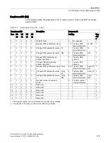
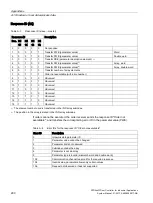
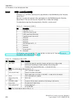
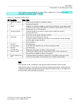
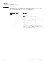
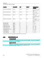
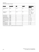
The following overview describes the relevant bits in status word 1. See also Figure 4-4
Sequential control state graph (Page 149).
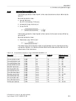
Table A- 22 Explanation of bits in ZSW1
Bit Description
Value Note
0
Ready for switching
on
1
Power supply switched on and system initialized
0
Not ready for switch on
1
Ready
1
Ready to run, system is switched on ("ON" command present), no fault active, system
can start as soon as the "Enable operation" command is given (see also STW1 bit 0)
0
Not ready to run, no "ON" command
2
Operation enabled
1
Operation enabled, drive order is executed (system follows the setpoints)
See also STW1 bit 3
0
Drive order is not executed, operation is locked
3
Fault active
1
Drive is faulty and therefore out of service.
The drive switches to "switching on inhibited" once the fault has been acknowledged
and the cause has been remedied
0
No fault present
4
No OFF2
(no coast down)
1
No OFF2 active
0
Coast down (deenergize) active, an OFF2 command is present
5
No OFF3
(no rapid stop)
1
No OFF3 active
0
Rapid stop (stop) active, an OFF3 command is present
6
Switch-on inhibit
1
Switching on inhibited, restart is only possible by means of OFF1 and then ON
0
No switching on inhibited, switching on is possible
9
Control requested by
PLC
1
Control requested, the automation system (PLC) is requested to take over control
0
Control is only possible on the device, the PLC is not the current controller
Note
The operation is also conditional on the operating mode of the door control system.
Initial mode is active in the event of a non-learnt or incorrectly learnt door. Normal mode is
not attained until both end positions have been determined after power on, and these end
positions match those that have been learnt.
Summary of Contents for SIDOOR ATD401W
Page 1: ......