Siemens Industry, Inc.
Building Technologies Division
P/N 315-050537-3
6
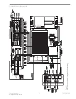
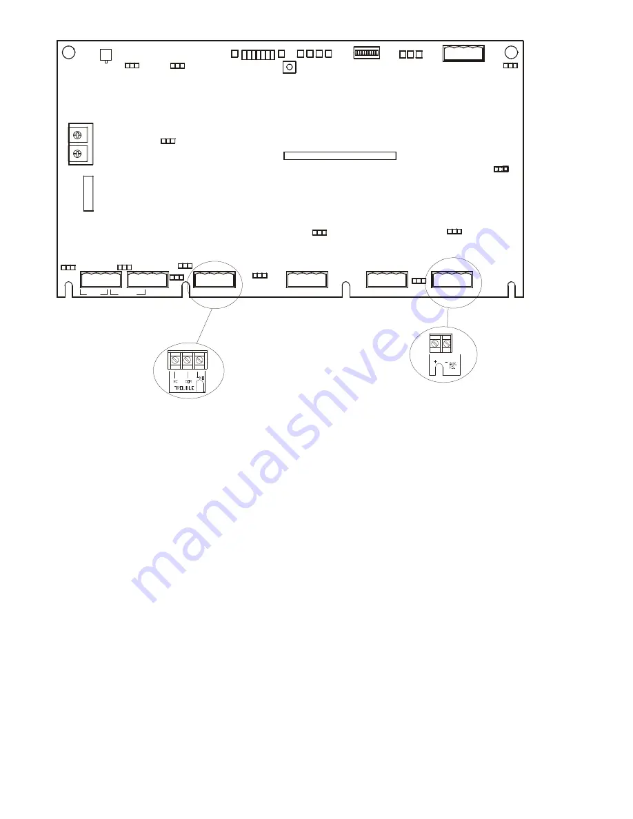
Figure 9
PAD-4-MB Layout
TB11
1+ 1-
2+
1
1
1
TB12
TB13
TB14
TB15
NAC3B
NAC4B (NAC2A)
_
+
_
+
NAC1B NAC2B (NAC1A)
_
+
_
+
J4
NC COM NO
NC
COM
2-
2
1
J5
1
1
1
TB16
J8
AUX PWR SUPPLY
_
+
J7
P1
J2**
S2
JP7
DS7
BAT
DS5
AUX/PS
DS8
PWR
DS6
DS1
OUT1
DS2
OUT2
DS3
OUT3
DS4
OUT4
J9
TB10
J10
J12
J14
J13
J11
RESET
10 9 8 7 6 5 4 3 2 1
ON
S1
J3
P2
SERVICE
PORT
J6
J16
NOT
USED
TROUBLE
1
B-
B+
INPUT 1
INPUT 2
DS11
BUSY
BRNOUT PSSI GND +24V
170W 10A
300W 20A
J1*
*J1 - Set Jumper J1 to 2-3 for normal operation
**J2 - Must be installed for Canadian installations. Must be removed for UL installations.
AUXILIARY POWER OUTPUT
3A MAX., 18-28 VDC
SUPERVISED, POWER LIMITED
COMMON TROUBLE
RELAY CONTACT
Auxiliary Power Supply Output
The auxiliary power supply output provides a 24VDC power source. It is supervised
for ground fault and short and is power limited. For applications where the battery
charger circuit charges batteries of 7.0 A.H. or less, or if the battery charger is dis-
abled, this output is limited to 3.0 amps maximum. For batteries between 15 A.H.
and 7.0 A.H., this output is limited to 1.5 amps maximum.
Common Trouble Relay
The UL approved power supply has a built-in Form C trouble relay. The trouble relay
will de-energize under a trouble condition. A typical application of the trouble relay is
to connect the UL approved power supply normally closed (N.C.) contacts in series
with an EOL of a spare IDC or NAC or monitor input from a fire alarm control unit.
This will cause a trouble on the fire alarm control unit when the UL approved power
supply opens its trouble contacts. The common trouble relay will be de-energized
after selectable delay (60-180 minutes) if AC is low or lost.
Note: The N.C. contact is the relay contact that is closed when the PAD-4 has power
and there are no trouble conditions.


