Siemens Industry, Inc.
Building Technologies Division
P/N 315-050537-3
12
•
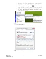
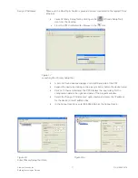
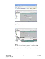
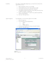
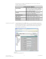
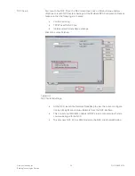
Download the configuration data to the switch
*
Select the device you want to configure in the left half of the
program window.
*
Click on the Download button (the second button from the left
in the tooolbar).
*
The IP Address is downloaded to the fiber switch.
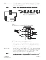
Figure 19
Download IP Address Configuration to Switch
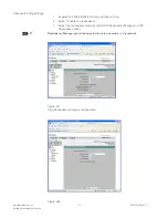
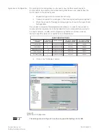
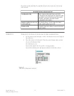
To configure either single or multimode fiber optic switch via WEB interface.
Fiber Optic Switch Settings
XNET over Ethernet
Style 7
uses ring topology to connect the switches on the
network. The two ends of the bus are closed to form a ring by the fiber switch
operating as a redundancy manager. The redundancy function is enabled and
disabled with the WEB interface.
In contrast to the ring ports of the other switches, the ring ports of the redundancy
manager are disconnected when the network is operating problem-free. The fiber
switch operating in the redundancy manager mode monitors the connected bus over
its ring ports. It switches the ring ports through if there is an interruption on the
connected bus. In other words, it restores a functioning bus over this substitute path.
Reconfiguration takes place within 0.3 seconds. As soon as the problem has been
eliminated, the original topology is restored—the ring ports in the redundancy
manager are once again disconnected from each other.
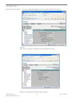
After the RM (Redundancy Manager) function has been enabled or after the RM has
been switched through, this is indicated by the RM LED on the housing.
Only one switch can be configured as a redundancy manager (Master) in a ring.
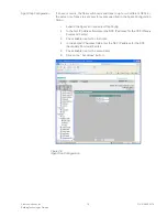
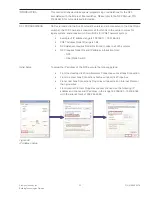
Follow the steps listed below to enable the redundancy manager.
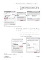
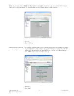
1.
Start Explorer and type the switch IP address in the URL field. For example:
http://192.168.1.101
2.
Type “admin” as user ID and “admin” as password. (The user is advised to
change the password.)
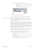
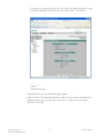
3.
Select the X204-2 icon if connected to multimode or the X204-2LD icon if
connected to single mode fiber optic switch.


