background image

Contents

Nur für den internen Gebrauch

 9034532, October 2009

4

HiPath Wireless Outdoor AP Installation Guide


bkTOC.fm

6.4  Brazil . . . . . . . . . . . . . . . . . . . . . . . . . . . . . . . . . . . . . . . . . . . . . . . . . . . . . . . . . . . . . . . . . . . . . . . . . . . . . .   50
6.5  ATEX, FM and cULus approvals  . . . . . . . . . . . . . . . . . . . . . . . . . . . . . . . . . . . . . . . . . . . . . . . . . . . . . . . .   50
6.6  NEMA 4X  . . . . . . . . . . . . . . . . . . . . . . . . . . . . . . . . . . . . . . . . . . . . . . . . . . . . . . . . . . . . . . . . . . . . . . . . . .   51

Summary of Contents for HiPath V6R1

Page 1: ...Communication for the open minded Siemens Enterprise Communications www siemens com open Documentation HiPath Wireless Outdoor AP V6R1 Installation Guide 9034532 ...

Page 2: ...ways apply as described or which may change as a result of further development of the products An obligation to provide the respective characteristics shall only exist if expressly agreed in the terms of contract Subject to availability Right of modification reserved The trade marks used are owned by Siemens Enterprise Communi cations GmbH Co KG or their respective owners Siemens Enterprise Commun...

Page 3: ...unting plate 18 3 5 1 Fitting the mounting plate to a wall 18 3 5 2 Screwing the cover plate to the mounting plate for the cable feedthrough 19 3 5 3 Fitting the mounting plate to an S7 standard rail 21 3 5 4 Fitting the mounting plate to a DIN rail 22 3 5 5 Fitting the mounting plate to a mast 23 3 5 6 Fitting the HiPath Wireless Outdoor AP to a mounting plate 24 4 Connecting cables to the HiPath...

Page 4: ...Contents Nur für den internen Gebrauch 9034532 October 2009 4 HiPath Wireless Outdoor AP Installation Guide bkTOC fm 6 4 Brazil 50 6 5 ATEX FM and cULus approvals 50 6 6 NEMA 4X 51 ...

Page 5: ... audience for this guide is field technicians who install the HiPath Wireless Outdoor APs 1 2 What is in this guide This guide contains the following Chapter 1 About this Guide describes the target audience the formatting conventions used in the guide and the safety information Chapter 2 Introduction provides an overview of the HiPath Wireless Outdoor APs their physical characteristics and the sco...

Page 6: ... example Type https hwc address mgmt port The following notes are used to draw your attention to additional information Note Notes identify useful information such as reminders tips or other ways to perform a task Danger Indicates that death or severe personal injury will result if proper precautions are not taken Warning Indicates that death or severe personal injury may result if proper precauti...

Page 7: ...conjunction with this documentation Commissioning and operation of a device system may only be performed by qualified personnel Within the context of the safety notes in this documentation qualified persons are defined as persons who are authorized to commission ground and label devices systems and circuits in accordance with established safety practices and standards Prescribed Usage Note the fol...

Page 8: ...scientific research is available with respect to proven health hazards which would throw doubt upon the scientific evaluation which serves as the basis for the ICNIRP safety concepts and the recommendations of the EU commission The SSK also concludes that below the current limit values these is also no scientific suspicion of health risks This assessment agrees with those of other national and int...

Page 9: ...s Outdoor APs to walls rails and poles The HiPath Wireless Outdoor AP supports the 802 11a 802 11g and full backward compatibility with legacy 802 11b devices It is delivered in a rugged enclosure and is available in two versions internal antenna and external antenna The HiPath Wireless Outdoor AP2660 with external antenna connectors supports a variety of antennas providing range and coverage vers...

Page 10: ...door AP package Five caps for the cover screws Depending on the version up to 8 plugs for sealing the housing Depending on the version up to 8 strain relief clamps One connector for the 48 V DC power supply A printed copy of the HiPath Wireless Outdoor AP Installation Instructions Confirm that each HiPath Wireless Outdoor AP package is complete If the package is not complete contact your supplier ...

Page 11: ...emaining LEDs are disabled Product Description Order ordered from Siemens A D Power Module PM2 Power Supply Input 110 240VACOutput 48VDC 6GK5791 2AC00 0AA0 Mounting Set MS1 Mounting material specifically for the HiPath Wireless Outdoor AP wall S7 300 and 35mm DIN rail Mastmontageple mounting 6GK5798 8MG00 0AA0 Antenna Mounting Tool IWLAN Antenna Mounting Tool 6GK5795 6MN01 0AA6 IWLAN Lightning Pro...

Page 12: ...o gain access to the reset button Figure 3 reset button with the housing cover removed The reset button is used to reset the HiPath Wireless Outdoor AP to its factory defaults For more information see the HiPath Wireless Controller Access Points and Convergence Software User Guide Warning You must remove the housing cover only after you have turned off the power supply of the HiPath Wireless Outdo...

Page 13: ...You have to remove the housing over if you want to carry out any of the following activities Mount the HiPath Wireless Outdoor AP to a wall or to the optional mounting plate Connect the power supply cables Ethernet cable or external antennas cable to the HiPath Wireless Outdoor AP Use the reset button on the HiPath Wireless Outdoor AP Figure 4 Removing the housing cover Warning You must remove the...

Page 14: ... using force otherwise the housing cover will be damaged 3 Remove the housing cover with the captive screws Position C in Figure 4 3 2 Fitting the housing cover Fitting the housing cover is carried out in the reverse order of the sequential steps of removing the housing cover The tightening torque for the cover screws is 1 8 Nm 3 3 Attaching cables 3 3 1 Attaching cables prior to mounting Before y...

Page 15: ...oor AP so that the opening in the wall is located above the lower edge of the device 3 3 2 Grounding terminal The chassis ground connector is located on the rear of the device M4 thread Connect the ground cable before you mount the HiPath Wireless Outdoor AP on the wall or on the optional mounting plate Once the Wireless AP is mounted the connector is no longer accessible Place the supplied toothe...

Page 16: ...nting only 9034532 October 2009 16 HiPath Wireless Outdoor AP Installation Guide 3 4 Mounting without an adapter wall mounting only 3 4 1 Drilling template The location of the holes for mounting the HiPath Wireless Outdoor AP on a wall is depicted in Figure 7 Figure 7 Drilling template for wall mounting ...

Page 17: ... mounting 2 Secure the HiPath Wireless Outdoor AP to the wall with three screws Position B Figure 8 The screws are not supplied with the device The type and length of the screws depend on the type of wall 3 4 1 1 Option Threaded holes on rear of housing When a wall is extremely thin it is often not possible to use wall plugs for the screws To allow wall mounting in this situation four M4 threaded ...

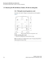
Page 18: ...utdoor AP with mounting plate 3 5 1 Fitting the mounting plate to a wall The location of the holes for fitting the mounting plate to a wall is depicted in Figure 9 Figure 9 Drilling template for fitting the mounting plate to a wall To fit the mounting plate to a wall Secure the mounting plate to the wall with four screws Note The screws are not supplied with the device The type and length of the s...

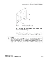
Page 19: ... seal is effective only when it is not subjected to spray water If the device is mounted on a wall no further measures are necessary When mounted in any other way an additional cover plate must be screwed to the mounting plate Warning If the cable feedthrough on the rear of the device is exposed to spray water degree of protection IP65 no longer applies In this case water can penetrate the device ...

Page 20: ...o screw the cover plate to the mounting plate for the cables feedthrough 1 Fit the cover plate on the mounting plate from below until the two lugs Position A in Figure 11 engage the lower edge of the mounting plate Figure 11 Fitting and securing the cover plate for the cable feedthrough 2 Secure the cover plate to the mounting plate with two M4 screws The screws are supplied with the assembly kit ...

Page 21: ... an S7 standard rail To fit the mounting plate to a S7 standard rail 1 Place the mounting plate with the two protruding catches on the top edge of the S7 standard rail Position A in Figure 12 Figure 12 Side view of a mounting plate on an S7 standard rail 2 At the bottom the mounting plate has two lugs with holes Screw the lugs to the S7 standard rail position B in Figure 12 The required screws are...

Page 22: ...3 5 4 Fitting the mounting plate to a DIN rail To fit the mounting plate to a DIN rail 1 Place the mounting plate with the two catches Position A in Figure 13 on the upper edge of the DIN rail Figure 13 Mounting plate with fittings for DIN rail mounting 2 Pull down the DIN rail sliding catch Position B in Figure 13 and press the mounting plate against the DIN rail until the sliding catch engages ...

Page 23: ... through the openings in the mounting plate position A in Figure 14 Figure 14 Mounting plate with fittings for mast mounting 2 Place the fastening straps around the mast at the required position 3 Feed the free end of the strap through the quick release fastener You can twist the tensioning screw Position B in Figure 14 to the side to adapt a fastening strap to the diameter of the mast 4 Press the...

Page 24: ...ables into the housing of the HiPath Wireless Outdoor AP Position A in Figure 15 For more information see Chapter 4 Connecting cables to the HiPath Wireless Outdoor AP Figure 15 Fitting the HiPath Wireless Outdoor AP to a mounting plate 2 Fit the HiPath Wireless Outdoor AP so that the upper edge of the rear of the housing is below the two catches of the mounting plate Position B in Figure 15 3 Pus...

Page 25: ...AP with mounting plate 9034532 October 2009 HiPath Wireless Outdoor AP Installation Guide 25 4 Screw the HiPath Wireless Outdoor AP using the three M4 screws supplied with the mounting plate Position C in Figure 16 tightening torque 1 8 Nm Figure 16 Screwing HiPath Wireless Outdoor AP to a mounting plate ...

Page 26: ...Mounting the HiPath Wireless Outdoor APs OutdoorAP_Description fm Mounting the HiPath Wireless Outdoor AP with mounting plate 9034532 October 2009 26 HiPath Wireless Outdoor AP Installation Guide ...

Page 27: ... Type no 919 545 and 919 506 holder Manufacturer DEHN SÖHNE GmbH Co KG Hans Dehn Str 1 Postfach 1640 D 92306 Neumarkt Germany Warning Antennas installed outdoors must be within the area covered by a lightning protection system Make sure that all conducting systems entering from outdoors can be protected by a lightning protection potential equalization system When implementing your lightning protec...

Page 28: ...364 4 41 is also possible if the generated rated voltage does not exceed the voltage limits 25 V AC or 60 V DC Caution There must be no potential difference between the following parts otherwise there is a risk that the device will be destroyed Ground potential of the power supply and ground potential of the antenna ground Ground potential of the power supply and a grounded housing Ground potentia...

Page 29: ... the NEC WARNING Cat Nos EAP Wx yy zx Canadian installation only TC cable type and manufacturer shall be specified Listed QPOR Type JZ 604 TC manufactured by Helukabel GmbH The TC cable for the power supply must be installed in areas of industrial establishments that are inaccessible to the public and in a manner that meets the requirements in Rule 12 2202 2 of the CEC Installed in conduit other s...

Page 30: ...led R SMA Male to SMA Male Ethernet IE FC TP Standard Cable GP 2 x 2 type A Order no 6XV1 840 2AH10 IE TP Torsion Cable 2 x 2 type C Order no 6XV1 870 2F IE FC TP Trailing Cable 2 x 2 type C Order no 6XV1 840 3AH10 Application Specification Table 3 Cable specification Warning If temperatures in excess of 70 degrees occur on the cable or at the housing socket or the temperature at the branching poi...

Page 31: ...P is subjected to spray water or dampness you will endanger your life Ensure that you adhere to the following safety rules Before connecting up turn off the power supply The sealing of the cable feedthroughs of the HiPath Wireless Outdoor AP is only assured when the cable has a suitable diameter and adequate tensile strength Only use cables that meet the specifications as mentioned in Section 4 1 ...

Page 32: ...110 230 V AC power supply You will require a power supply adapter to use this power supply 2 Fit a strain relief clamp to the connected cable The toothed part of the clamp must enclose the cable completely is depicted by Position B Figure 17 3 Press the strain relief clamp into the housing until the cable is located completely in the opening in the housing seal Position C in Figure 17 4 Seal all o...

Page 33: ... alternative the voltage can be modulated onto the data lines phantom power If Fast Connect Ethernet connectors are used to allow assembly in the field or due their greater mechanical strength only four wire cables can be used In this case only phantom power is possible This does not represent a restriction for the user since PoE compatible power supply equipment must always provide both options T...

Page 34: ...ess the connector into the socket in the housing until it engages 3 Secure the power cable with a strain relief clamp 4 4 Fitting a power supply adapter The HiPath Wireless Outdoor AP supports only the 110 230 V AC power supply adapter Warning Power supply cables may only be connected when the power is turned off Start up the HiPath Wireless Outdoor AP only after screwing the housing cover in plac...

Page 35: ... must make contact with the inner surface of the HiPath Wireless Outdoor AP Figure 21 Using a power supply adapter in a HiPath Wireless Outdoor AP 2 Connect the power supply adapter and the HiPath Wireless Outdoor AP with the screw supplied with the power supply adapter position A in Figure 21 3 Connect the cable for the power supply The assignment of the contacts is depicted in Figure 21 4 Secure...

Page 36: ...nector on the rear of the power supply adapter from the socket in the housing and remove the power supply adapter 4 5 Connecting an Ethernet cable to the HiPath Wireless Outdoor AP You can connect the Ethernet cable to the HiPath Wireless Outdoor AP s RJ 45 jack To connect an Ethernet cable to the HiPath Wireless Outdoor AP 1 Insert the connector of the Ethernet cable in the corresponding socket o...

Page 37: ...able into the R SMA socket and tighten the sleeve nut on the socket key size SW8 tightening torque 0 6 Nm Note First connect the cable for antenna B if you want to use two antennas for an interface Once the cable for antenna A is connected it is difficult to reach socket B Figure 23 Ports for external antennas with the housing cover removed Note R1 is mapped to radio 802 11a and R2 is mapped to ra...

Page 38: ...ng cables to the HiPath Wireless Outdoor AP OutdoorAP_ConnectingUp fm Connecting an external antenna cable to the HiPath Wireless Outdoor AP 9034532 October 2009 38 HiPath Wireless Outdoor AP Installation Guide ...

Page 39: ...ectors Data Transfer Interfaces Electrical Data Ethernet Transfer Rate 10 100Mbps Wireless Transmission Rate 1 54 Mbps Power Supply Standards Supported 802 3af Power over Ethernet Table 7 Data Transfer Power 48 V DC supply via supplied connector RJ 45 jack Power over Ethernet 48 V DC 110 230 V AC with optional power supply adapter available as accessory Data RJ 45 jack for Ethernet 1 x 2 BFOC sock...

Page 40: ...egulations an approval may be required by the local regulatory authorities The table Permitted antennas provides the list of third party antennas that are permitted Note When you select third party permitted antennas you must set the antenna s power according to the table Antenna channel power settings Dimensions WxHxD 251 mm x 251 mm x 72 mm Weight Without power supply adapter 2241 g With power s...

Page 41: ...ining special programming and antenna and cable installations Application The intended use is generally not for the general public Instead it is generally for industry commercial use Characteristics Antenna and Type Frequency GHz Antenna gain dBi Impedence Ω Order No ordered from Siemens A D Omni Antenna 1 ANT795 6MN 2 4 6 50 6GK5795 6MN00 0AA6 5 8 Omni Antenna 2 ANT792 6MN 2 4 6 50 6GK5792 6MN00 ...

Page 42: ...x power from the values listed in table Antenna channel power information Do not select a higher power than the value listed in table Antenna channel power settings 5 2 1 Antenna channel power settings FCC IC To fulfill all the requirements according to FCC Part 15 24 and RSS 210 the following software power setting is necessary Mode Channels Antenna 1 ANT785 6MN Antenna 2 ANT792 6MN Antenna 4 ANT...

Page 43: ...ting is necessary Mode Channels Antenna 1 ANT795 6MN Antenna 3 ANT793 6MN Antenna 4 ANT795 6DN Antenna 8 ANT793 4MN 802 11a 36 20 17 14 20 40 48 20 17 17 20 Table 16 Antenna channel power settings Mode Channels Antenna 1 ANT795 6MN Antenna 3 ANT793 6MN Antenna 4 ANT795 6DN Antenna 6 ANT793 8DN Antenna 8 ANT793 4MN 802 11a 149 161 20 20 20 11 20 Table 17 Antenna channel power settings Mode Channels...

Page 44: ... for this transmitted must be installed to provide a separation distance of at lease 20 cm from all persons and must be co located or operating in conjunction with another antenna or transmitter Mode Channels Antenna 1 ANT795 6MN Antenna 3 ANT793 6MN Antenna 4 ANT795 6DN Antenna 6 ANT793 8DN Antenna 8 ANT793 4MN 802 11a 36 48 11 14 11 5 14 52 64 14 17 14 5 17 100 140 20 20 20 8 20 Table 19 Antenna...

Page 45: ...f the Council on radio equipment and telecommunications terminal equipment and the mutual recognition of their conformity Conformity with the basic requirement of the directive is attested by adherence to the following standards EN 60950 1 Safety of information technology equipment EN 301489 1 V1 6 1 Electromagnetic compatibility for radio equipment and services EN 301489 17 V1 2 1 Specific requir...

Page 46: ...the responsible authorities according to the above mentioned EC Directive at the following address Siemens Aktiengesellschaft Automation and Drives Industrielle Kommunikation Postfach 4848 D 90327 Nürnberg This declaration certifies compliance with the directives named above but does not guarantee any specific properties European spectrum usage rules The Wireless AP configured with approved antenn...

Page 47: ...license Hungary Indoor only Indoor only Indoor or outdoor Indoor or outdoor Iceland Indoor only Indoor only Indoor or outdoor Indoor or outdoor Ireland Indoor only Indoor only Indoor or outdoor Indoor or outdoor Italy Indoor only Indoor only Indoor or outdoor Indoor Outdoor w license Latvia Indoor only Indoor only Indoor or outdoor Indoor or outdoor Liechtenstein Indoor only Indoor only Indoor or ...

Page 48: ...oved by SIEMENS may void the FCC authorization to operate this equipment This equipment has been tested and found to comply with the limits for a Class B digital device pursuant to Part 15 of the FCC Rules These limits are designed to provide reasonable protection against harmful interference in a residential installation This equipment generates uses and can radiate radio frequency energy and if ...

Page 49: ... the United States the system must be professionally installed to ensure compliance with the Part 15 certification It is the responsibility of the operator and professional installer to ensure that only certified systems are deployed in the United States The use of the system in any other combination such as co located antennas transmitting the same information is expressly forbidden 6 3 Industry ...

Page 50: ... devices 6 4 Brazil Operation is limited to the following 5 15 5 25 GHz channels 36 40 44 and 48 2 4 2 4835 GHz channels 1 to 13 6 5 ATEX FM and cULus approvals The products HiPath Wireless Outdoor AP2650 and HiPath Wireless Outdoor AP2660 have the following approvals EN 60079 15 2005 EN 60079 0 2006 II 3 G Ex nA II T4 KEMA 07 ATEX 0203 X Ta 40 C to 60 C FM 3611 CL 1 Div 2 GP A B C D T4 CL 1 Zone ...

Page 51: ... to 60 C Note The specified approvals apply only when the corresponding mark is printed on the product 6 6 NEMA 4X The products HiPath Wireless Outdoor AP2650 and HiPath Wireless Outdoor AP2660 have the following approval NEMA 250 2003 Note The requirements are only met if the device is screwed to a mounting plate and a cover plate for the cable feedthrough For more information see Section 3 5 Mou...

Page 52: ...Certification OutdoorAP_Certification fm NEMA 4X 9034532 October 2009 52 HiPath Wireless Outdoor AP Installation Guide ...

Page 53: ...ing plate to S7 standard rail 21 mounting plate to wall 18 power supply adapter 34 fitting housing cover 14 formatting conventions 6 G grounding terminal 15 guide about this 5 what is in it 5 who should use it 5 H HiPath Wireless Outdoor AP connecting 48 V DC 33 connecting cables 27 connecting ethernet cable 36 connecting external antenna cable 37 fitting it to mounting plate 24 list of accessorie...

Page 54: ...sage 7 product overview 9 Q qualified personnel 7 R removing housing cover 13 power supply adapter 36 reset button 12 S safety extra low voltage 28 information 7 rules 31 screwing cover plate to mounting plate for cable feedthrough 19 T technical specifications 39 terminal grounding 15 W what is in this guide 5 who should use this guide 5 ...

Reviews: