


OutdoorAP_ConnectingUp.fm
Connecting cables to the HiPath Wireless Outdoor AP
Connecting an external antenna cable to the HiPath Wireless Outdoor AP
9034532, October 2009
HiPath Wireless Outdoor AP Installation Guide
37
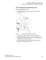
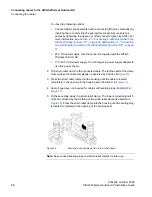
4.6 Connecting an external antenna cable to the HiPath Wireless Outdoor
AP
For each WLAN port, there are two R-SMA sockets on the HiPath Wireless
Outdoor AP to connect external antennas.
Figure 23
shows how the R-SMA
sockets are assigned to the WLAN ports.
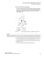
To connect an external antenna cable to the HiPath Wireless Outdoor AP:
1. Insert the connector on the antenna cable into the R-SMA socket and tighten
the sleeve nut on the socket (key size SW8), tightening torque 0.6 Nm.
Note:
First connect the cable for antenna "B" if you want to use two antennas
for an interface. Once the cable for antenna "A" is connected, it is difficult to
reach socket "B".
Figure 23
Ports for external antennas, with the housing cover removed
Note:
“R1” is mapped to radio 802.11a and “R2” is mapped to radio 802.11b/
g on the user interface of the HiPath Wireless Controller.
The Antenna “A” connector is mapped to the Right antenna and the Antenna
“B” connector is mapped to the Left antenna on the user interface of the
HiPath Wireless Controller.
2. Screw a terminating resistor to the unused socket if you use only one antenna
on a port.
3. Secure the antenna cable(s) with a strain relief clamp.