English
5/5
Siemens plc 1993
5.3 Parameterisation
5.3.1 Parameter Setting
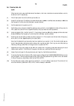
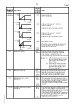
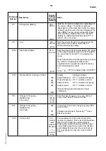
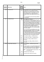
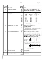
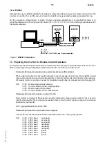
To match the inverter to a particular motor/installation, various digital parameters can be adjusted. The procedure
for adjustment is described below:
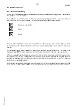
Remove the small cover directly below the LED viewing window by inserting a small blade screwdriver into the slot
provided and levering the cover upwards. This will reveal the parameterisation push–buttons:
P
Parameter push–button
Raise
Lower
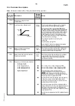
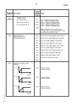
Carry out parameterisation with mains power applied to the inverter. Some parameters can be adjusted while the
drive is running
(see 5.3.2). If adjustment of a parameter is not permitted, the display will flash when the buttons are
pressed.
The parameter number mode is obtained by pressing the parameter (P) push–button once. This results in the
display showing P00. The desired parameter can then be selected using the raise and lower push–buttons.
When the parameter push–button is pressed again, the contents of the selected parameter memory is displayed.
The value can then be adjusted using the raise and lower push–buttons. When the desired value has been
selected, pushing the parameter button again loads the new value into non–volatile memory and the display once
again shows the parameter number.
When all the required parameter settings have been loaded in, return to normal operating mode by selecting P00
and then pressing P. The display will then revert to its normal frequency/output current or fault code indication.
Summary of Contents for 6SE2101-1AA01
Page 5: ...English vi Siemens plc 1993 This page intentionally blank ...
Page 11: ...English 2 2 Siemens plc 1993 This page intentionally blank ...
Page 53: ...English 7 18 Siemens plc 1993 This page intentionally blank ...
Page 59: ...Deutsch vi Siemens plc 1993 Diese Seite bleibt absichtlich frei ...
Page 65: ...Deutsch 2 2 Siemens plc 1993 Diese Seite bleibt absichtlich frei ...
Page 107: ...Deutsch 7 18 Siemens plc 1993 Diese Seite bleibt absichtlich frei ...


