English
8/2
Siemens plc 1993
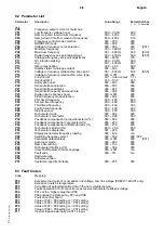
8.2 Parameter List
Parameter
Description
Value Range
Default Settings
[ ] – N. America
Only
P00
Frequency, output current or fault code
P01
Low frequency voltage boost
00.0 – 30.0%
00.0
P02
Ramp–up time to maximum frequency
00.0 – 400 s
10.0
P03
Ramp–down time from maximum frequency
00.0 – 400 s
10.0
P04
Frequency control mode selection
000 – 009
000
P05
RUN/STOP mode
000 – 009
000
P06
Voltage to frequency curve selection
000 – 006
000
[001]
P07
Minimum frequency
00.0 – 399 Hz
00.1
P08
Maximum frequency
00.1 – 400 Hz
50.0
[60.0]
P09
Digital frequency set–point adjustment
00.0 – 400 Hz
50.0
[60.0]
P10
Analogue frequency set–point adjustment
080 – 240%
100
P11
DC injection braking
00.0 – 20.0%
00.0
P12
Jog
00.1 – 400 Hz
05.0
P13
Slip compensation
00.0 – 20.0
00.0
P14
Display status / Analogue output
000 – 003
000
P15
Voltage to frequency relationship: knee point
00.1 – 400 Hz
50.0
[60.0]
P16
Voltage to frequency relationship: curve type
000 or 001
000
P17
Current limit
00.1 – rated output
1.1 x
P18
Overload limit
01.0 – 03.0
01.5
P19
Automatic boost
000 – 003
000
P20
Serial interface selection
000 – 003
000
P21
Serial interface address
000 – 030
000
P22
Serial interface parity and baud rate
000 – 008
000
P23
Digital input response speed
000 or 001
000
P24
Fixed frequency mode selection
000 – 002
000
P25
First fixed frequency
00.0 – 400
00.0
P26
Second fixed frequency
00.0 – 400
00.0
P27
Third fixed frequency
00.0 – 400
00.0
P28
Fourth fixed frequency
00.0 – 400
00.0
P29
Skip frequency
00.0 – 400
00.0
P30
Tachometer mode
000 – 004
000
P31
Tachometer scale factor
00.1 – 999
50.0
P32
Feedback compensation: proportional term (%)
000 – 999
050
P33
Feedback compensation: integral term (%)
000 – 250
000
P34
Feedback compensation: differential term (%)
000 – 250
000
P35
Tachometer slip limit (Hz)
00.0 – 20.0
05.0
P36
Tachometer sample rate
001 – 200
001
P37
Display tachometer frequency reading
000 – 400
n/a
P40
Switching frequency select
000 – 002
000 / 002
P41
Parameter default values
000 or 001
000
[001]
P42
Auto reset mode
000 – 002
000
P43
Ramp Smoothing
000 – 100
000
P44
Tachometer Interface Unit
000 – 004
000
P45
Clear Text Operator Panel Language
000 or 001
n/a
P48
Fault code
000 – 011
n/a
P49
Hardware type
P50
Software version
P51
Customer–specific Variants
000 – 255
000
8.3 Fault Codes
Code
Meaning
F00
Excessive load current or excessive link voltage. Low line voltage (6SE210*–3AA01 only).
F01
Excessive heatsink temperature.
F02
Corruption of parameterisation data in the non–volatile memory.
F03
Faulty operation of A–D converter or excessive tachometer feedback voltage.
F04
P07 set to a higher value than P08.
F05
P09 outside the limits set by P07 and P08.
F06
Fault on control board.
F07
Value of P25 > P08 setting or < P07 setting.
F08
Value of P26 > P08 setting or < P07 setting.
F09
Value of P27 > P08 setting or < P07 setting.
F10
Value of P28 > P08 setting or < P07 setting.
F11
Inverter tripped externally via X11.4 input.
Summary of Contents for 6SE2101-1AA01
Page 5: ...English vi Siemens plc 1993 This page intentionally blank ...
Page 11: ...English 2 2 Siemens plc 1993 This page intentionally blank ...
Page 53: ...English 7 18 Siemens plc 1993 This page intentionally blank ...
Page 59: ...Deutsch vi Siemens plc 1993 Diese Seite bleibt absichtlich frei ...
Page 65: ...Deutsch 2 2 Siemens plc 1993 Diese Seite bleibt absichtlich frei ...
Page 107: ...Deutsch 7 18 Siemens plc 1993 Diese Seite bleibt absichtlich frei ...

