English
7/3
Siemens plc 1993
7.4 Simple Protocol
The inverter is a slave device, hence it always listens and only transmits when replying to a ‘message’ received
from the master device.
The inverter only responds to messages containing its device number or to broadcast messages. The inverter
always sends a reply to its own messages but never replies to a broadcast message.
A message consists of 11 bytes, with each byte transmitted as 11 bits. Each transmitted byte has the following
structure:
1 start bit
8 data bits
1 parity bit
1 stop bit
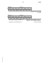
The message is constructed from 11 bytes in the following manner:
STX
Device
Data
Data
Data
Data
Data
Data
Data
Data
BCC
Number
byte 1
byte 2
byte 3
byte 4
byte 5
byte 6
byte 7
byte 8
byte
STX is the ASCII character value 02.
The device number is 0 to 30. Device number 31 indicates a broadcast message.
The data bytes are described in detail in sections 7.6 and 7.7 and are different for received and transmitted
messages.
The BCC checksum is a single byte checksum is calculated by exclusive ORing all of the previous 10 bytes in the
message.
If the inverter receives an invalid message, it is discarded and the inverter waits for the remote control device to
retransmit the message.
If the inverter receives a valid message addressed to it then it will act upon the data contained in the message and
send a reply message back to the remote control device.
7.4.1 Using the Simple Protocol
The 6SE21 inverter may be in one of the following states when controlled via the remote control link:
OFF
– inverter is inactive
ON
– inverter is active
LOCKED
– inverter is locked and inactive
UNLOCKED
– inverter is not locked
STOPPED
– inverter is active but stopped
RUNNING
– inverter is active and running
TRIPPED
– inverter is inactive and is awaiting a trip acknowledge
7.4.1.1 Enabling the Serial Link
When serial control is enabled (parameter P20 set to 001) the inverter is LOCKED and OFF. Before the inverter can
be controlled it must be unlocked and switched on.
To unlock the inverter set the LOCKED bit in the transmit message.
To switch on the inverter, send a message with the OFF/ON bit set to zero followed by a message with the OFF/ON
bit set to 1.
The inverter is now ready to run.
Summary of Contents for 6SE2101-1AA01
Page 5: ...English vi Siemens plc 1993 This page intentionally blank ...
Page 11: ...English 2 2 Siemens plc 1993 This page intentionally blank ...
Page 53: ...English 7 18 Siemens plc 1993 This page intentionally blank ...
Page 59: ...Deutsch vi Siemens plc 1993 Diese Seite bleibt absichtlich frei ...
Page 65: ...Deutsch 2 2 Siemens plc 1993 Diese Seite bleibt absichtlich frei ...
Page 107: ...Deutsch 7 18 Siemens plc 1993 Diese Seite bleibt absichtlich frei ...

