


2
8
4
7
3
5
6
1
OSSD1
OSSD2
24 V DC
0 V DC
/
4
1
2
3
5
2
8
4
7
3
5
6
1
OSSD1
OSSD2
/
4
1
2
3
5
2
8
4
7
3
5
6
1
OSSD1
OSSD2
/
4
1
2
3
5
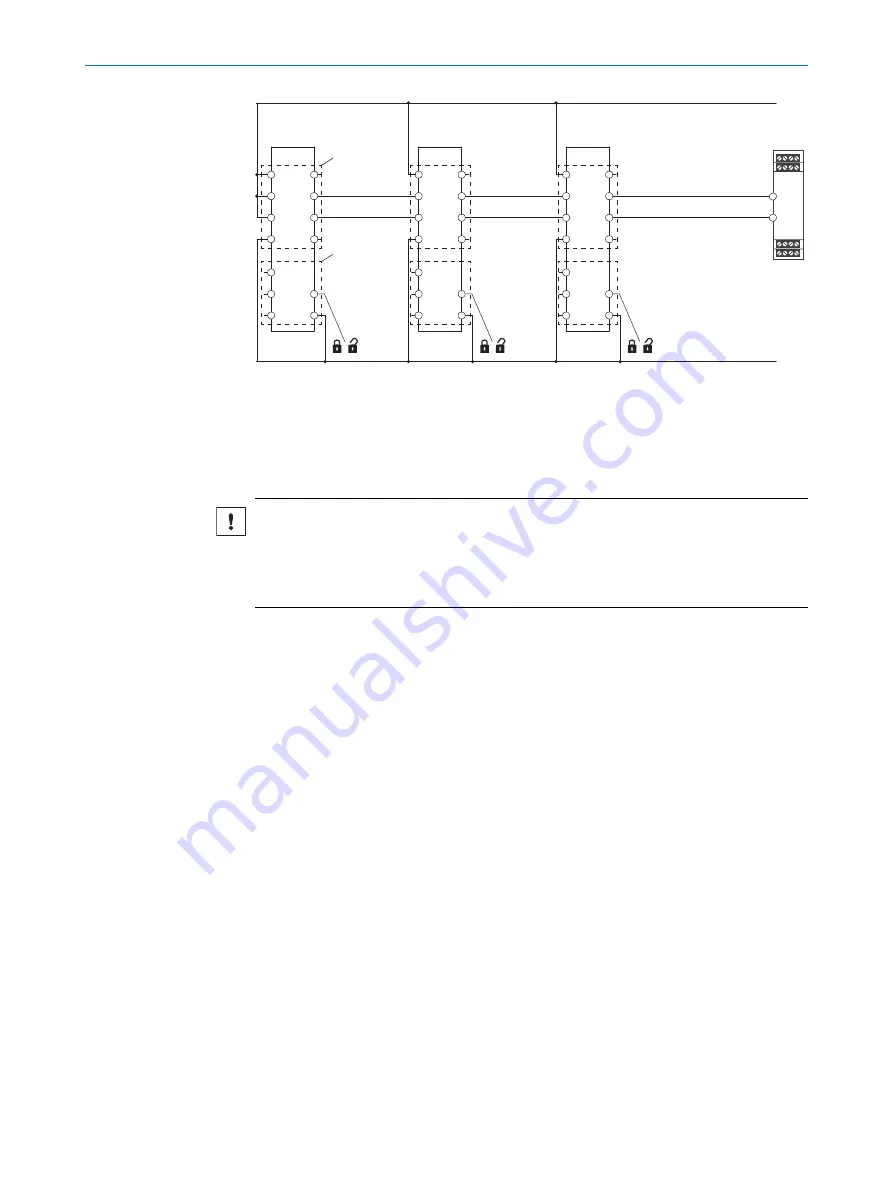
Figure 16: Safe series connection
1
TR110 Lock
2
Safe evaluation unit
3
Male connector, M12, 8-pin
4
Male connector, M12, 5-pin
NOTICE
•
Connect the enable inputs of the OSSDs In 1 and In 2 directly to a power supply
unit (+24 VDC) or to the outputs OSSD 1 and OSSD 2 of another TR110 Lock
safety locking device.
•
There must not be any clocked controller signals at inputs In 1 and In 2.
The maximum number of safety locking devices depends on the following factors:
•
Applied supply voltage
•
Length of cables used
•
Cable cross-section of cables used
•
Load current
The voltage drop in the safe series connection has to be checked so that the defined
minimum voltage is still applied to the last safety locking device.
The number of safety locking devices in a safe series connection influences the
response time of the system (
The safe series connection can be implemented using special T-connectors and an end
connector (
see "Connection of a safe series connection", page 32
).
4.4.6
Protection of the voltage supply
The voltage supply must be provided with fuse protection depending on the number of
safety locking devices and the required current for the outputs.
Max. current consumption of a single safety locking device I
max
:
I
max
= I
TR110
+ I
OSSD1
+I
OSSD2
+ I
OAUXL
+ I
OAUXD
I
TR110
= Operating current of the TR110 Lock safety locking device
I
OSSD1
= Load current of OSSD 1 (max. 150 mA)
I
OSSD2
= Load current of OSSD 2 (max. 150 mA)
I
OAUXL
= Load current of locking function application diagnostic output (max. 50 mA)
4
PROJECT PLANNING
22
O P E R A T I N G I N S T R U C T I O N S | TR110 Lock
8023119/15LY/2019-10-28 | SICK
Subject to change without notice


