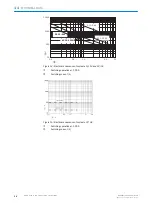
Test pulse width
2 ms
Length of cable (single)
≤ 100 m
Cable resistance
≤ 10 Ω
Table 11: Electrical data - application diagnostic output (Y1, Y2)
Type of output
Push-pull semiconductor output, short-circuit
protected
Output voltage HIGH:
(U
V
– 3 V) … U
V
Output voltage LOW:
0 V … 3 V
Input current (NPN)
≤ 15 mA
Output current (PNP)
≤ 120 mA
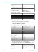
Table 12: Electrical data - enabling current paths (13, 14, 23, 24, 37, 38)
Response time when EMSS sensor type is configured
Dual-channel switch-off with positive open‐
ing normally closed contacts
≤ 12 ms
Dual-channel switch off (without positive
opening, e.g. reed switch)
≤ 16 ms
Response time when OSSD sensor type is con‐
figured
≤ 12 ms
Release delay between enabling current paths
and release-delay enabling current path
Configured release delay ± 10 %
Contact type
Positively guided
Contact material
Silver alloy, gold flash plated
Sum current
≤ 12 A
Minimum switch-off time
1)
300 ms
Mechanical service life
10 × 10
6
switching operations
Max. short-circuit protection
≤ 400 A
1)
Time the enabling current paths of the safety relay remain open before closing again.
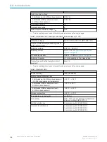
Table 13: Electrical data - enabling current paths (13, 14, 23, 24)
Utilization category
AC-15: 230 V, 5 A (IEC 60947-5-1)
DC-13 (0,1 Hz): 24 V, 4 A (IEC 60947-5-1)
Number of enabling current paths, not delayed
(normally open, safe)
2
Switching voltage
At altitudes below 2,000 m above sea level
10 V DC … 230 V DC
10 V AC … 230 V AC
At altitudes 2,000 m above sea level …
4,000 m above sea level
10 V DC … 150 V DC
10 V AC … 150 V AC
Switching current
10 mA … 6 A,
DC switching capacity
0.1 W … 200 W,
AC switching capacity
0.1 VA … 1500 VA
Switching frequency
≤ 1 Hz
Contact fuse with safety fuse gG or circuit
breaker C
Max. 6 A
TECHNICAL DATA
11
8024303/2019-12-18 | SICK
O P E R A T I N G I N S T R U C T I O N S | ReLy TIME1
31
Subject to change without notice

