


•
2 application diagnostic outputs (not safe)
•
3 test outputs (not safe)
3.2.3
Compatible sensor types
The safety relay is suitable for:
•
Safety sensors and safety switches with volt-free output contacts (EMSS), e.g.:
Dual-channel safety command devices (emergency stop pushbuttons, rope pull
switches, etc.), dual-channel contact-based interlocking devices (safety locking
devices and safety switches) and dual-channel magnetic safety switches with reed
contacts
•
Safety sensors and safety switches with OSSD output, e.g.: Electro-sensitive pro‐
tective equipment (ESPE) with a single-channel or dual-channel monitored active
switching output with cross-circuit detection (OSSD)
3.2.4
Release-delayed enabling current paths
The release-delayed enabling current path opens with a set delay time.
3.2.5
Restart interlock
A restart interlock can be implemented with a reset pushbutton.
3.2.6
External device monitoring
Permanent external device monitoring can be implemented using external wiring.
3.2.7
Cross-circuit detection
A cross-circuit is detected on the safety capable inputs if the “Contacts” sensor type is
configured.
3.2.8
Status indicators
LEDs
R
E
L
Y
PWR
OUT
13
23
I1
Y1
14
24
I2
Y2
A2
S1
37
A1
38
X1
X2
R1
PWR
OUT
13
23
I1
Y1
14
24
I2
Y2
A2
R1
A1
S1
X1
X2
TIME1
1100688
R
E
L
Y
37
38
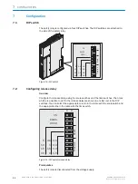
Figure 2: LEDs
The labeled positions are only partially assigned LEDs. The positions and their labeling
(except for the upper 2 lines) also show the pin assignment of the terminals on the front
connector.
3
PRODUCT DESCRIPTION
10
O P E R A T I N G I N S T R U C T I O N S | ReLy TIME1
8024303/2019-12-18 | SICK
Subject to change without notice


