


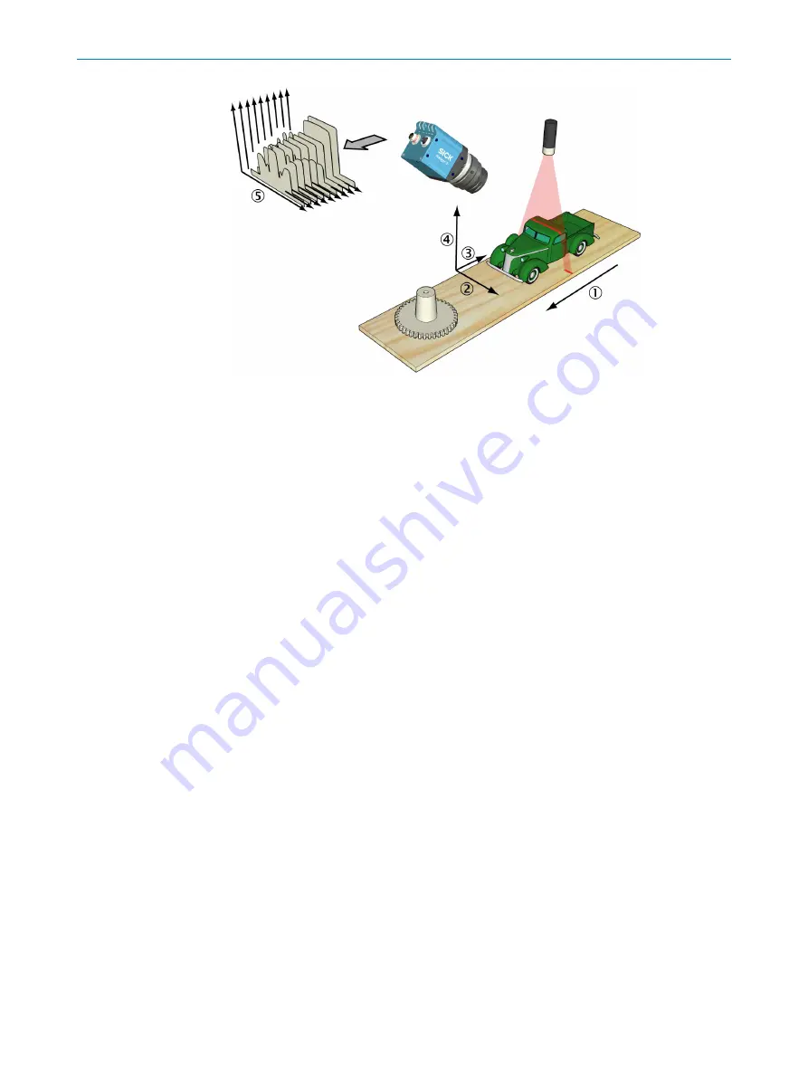
Figure 2: Measuring the range of a cross-section of an object
1
Transportation direction
2
X (width)
3
Y (negative transport direction)
4
Z (range)
5
Profiles
By default, the range measurement values from the camera are not calibrated – that is:
•
X and Z (range) coordinates are represented by column and row positions on the
sensor, instead of real world positions and distances.
•
Y coordinates are represented for example by the sequence number of the mea‐
surement, or by the encoder value for when the profile was captured.
In a machine vision system, the Ranger3 camera acts as a data streamer. It is con‐
nected to a PC through a Gigabit Ethernet network. The camera sends the profiles to
the computer, and the computer runs a custom application that retrieves the profiles
and processes the measurement data in them.
Before the camera can be used in a machine vision system, the following needs to be
done:
•
Find the right way to mount the camera and lighting.
•
Configure (and optionally calibrate) the camera to make the proper measure‐
ments.
•
Write the application that retrieves and processes the profiles sent from the cam‐
era.
For more information about 3D measurements,
.
3.3
Hardware description
3.3.1
Sensor
The Ranger3 camera is based on a unique SICK CMOS sensor which has a 2D pixel
matrix, row-parallel AD-converters, and a processor architecture that enables image
processing directly on the sensor. The technology is called ROCC, which means Rapid
On-Chip Calculation. For technical details,
.
3
PRODUCT DESCRIPTION
12
O P E R A T I N G I N S T R U C T I O N S | Ranger3
8020774/14IM/2019-07 | SICK
Subject to change without notice


