


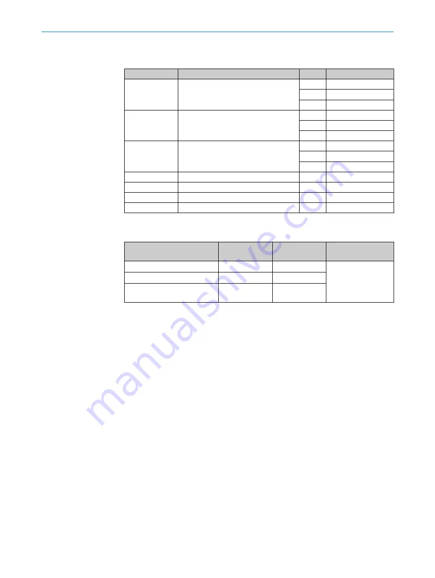
Connections - pin assignment
Table 25: Connections - pin assignment
Plug
Assembly
Pin
Assignment
TUBE 1
Sample gas line 1
1
L (L)
2
N (L)
3
PE
FILTER1
Gas sampling unit filter 1
(Lines from hose bundle line)
1
L (L)
2
N (L)
3
PE
PROBE1
Gas sampling unit probe tube 1
(Lines from hose bundle line)
4
L (L)
5
N (L)
6
PE (not connected)
TUBE2
Sample gas line 2
1 ... 3
As for TUBE1
FILTER2
Gas sampling unit filter 2
1 ... 3
As for FILTER1
PROBE2
Gas sampling unit gas sampling probe 2
4 ... 6
As for PROBE1
TUBE3
Sample gas line 3
1 ... 3
As for TUBE1
1
The connections must match the connections on the gas sampling unit.
Table 26: Connection terminal - external heater outputs on the analyzer
Wire
Cross-section in
mm
2
Cross-section in
AWG
Tightening torque Nm
rigid
0.2 ... 4.0
24 ... 10
0.5 ... 0.6
flexible with ferrules
0.25 ... 4.0
24 ... 10
flexible with ferrules with insu‐
lating collar
0.25 ... 4.0
24 ... 10
13
TECHNICAL DATA
68
O P E R A T I N G I N S T R U C T I O N S | MCS200HW
8021889/1D1T/V3-1/2021-09 | SICK
Subject to change without notice