


Important information
NOTICE
•
Install an external power disconnection unit which disconnects all connectors and
fuses near the analyzer.
•
The power disconnection unit must be marked clearly and be easily accessible.
•
The onsite wiring system to the power source of the system must be installed and
fused according to the relevant regulations.
•
Always connect a protective ground to PE.
Procedure
1.
Guide the electric lines through the screw connections of the housing.
2.
Connect the electric lines.
6.6
Performing a high voltage test
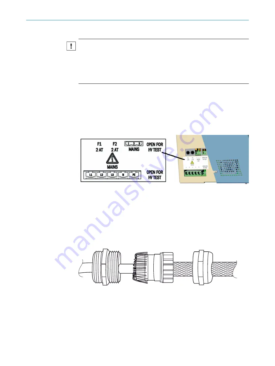
Overview
UPS
Figure 13: Power supply connections
Procedure
1.
To avoid erroneous measurements during a high-voltage test, the bridges descri‐
bed in Figure
must be removed.
2.
Insert the bridges again after the high-voltage test.
6.7
Connecting the signal line (option)
Overview
Figure 14: Signal lines connections (shielded)
Connect the signal lines according to the wiring diagram.
Procedure
1.
Guide the line through the housing duct.
2.
Attach the shielding according to the Figure
6
ELECTRICAL INSTALLATION
32
O P E R A T I N G I N S T R U C T I O N S | MCS200HW
8021889/1D1T/V3-1/2021-09 | SICK
Subject to change without notice