


Procedure
1.
Push the tube into the tube screw fitting to the stop.
2.
During initial fitting: Hold the fitting bolt steady and tighten the cap nut with 1 1/4
revolutions.
3.
During further fittings: Tighten the cap nut to the previous position (the resistance
increases noticeably) and then tighten slightly.
5.4.4
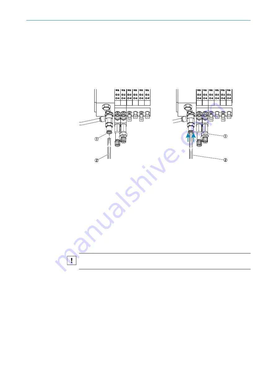
Using a push-in fitting (pneumatic)
Overview
Figure 9: Push-in fitting with retaining ring (example shown)
1
Retaining ring
2
Tube
Procedure
Fitting the tube
1.
Push the tube in.
Removing the tube
1.
Press the retaining ring in.
2.
Pull the tube out.
5.4.5
Laying the hose bundle line
Important information
NOTICE
Protect the line from damage (chafing through vibration, mechanical load).
Procedure
1.
Lay the hose bundle line from the gas sampling unit to the measuring device.
°
An additional length of 0.5 m is required at the gas sampling unit for the
internal lines.
°
An additional length of 3.5 m is required from the installation plate for the
internal lines.
2.
Observe a minimum bending radius of 300 mm.
5
MOUNTING
26
O P E R A T I N G I N S T R U C T I O N S | MCS200HW
8021889/1D1T/V3-1/2021-09 | SICK
Subject to change without notice