


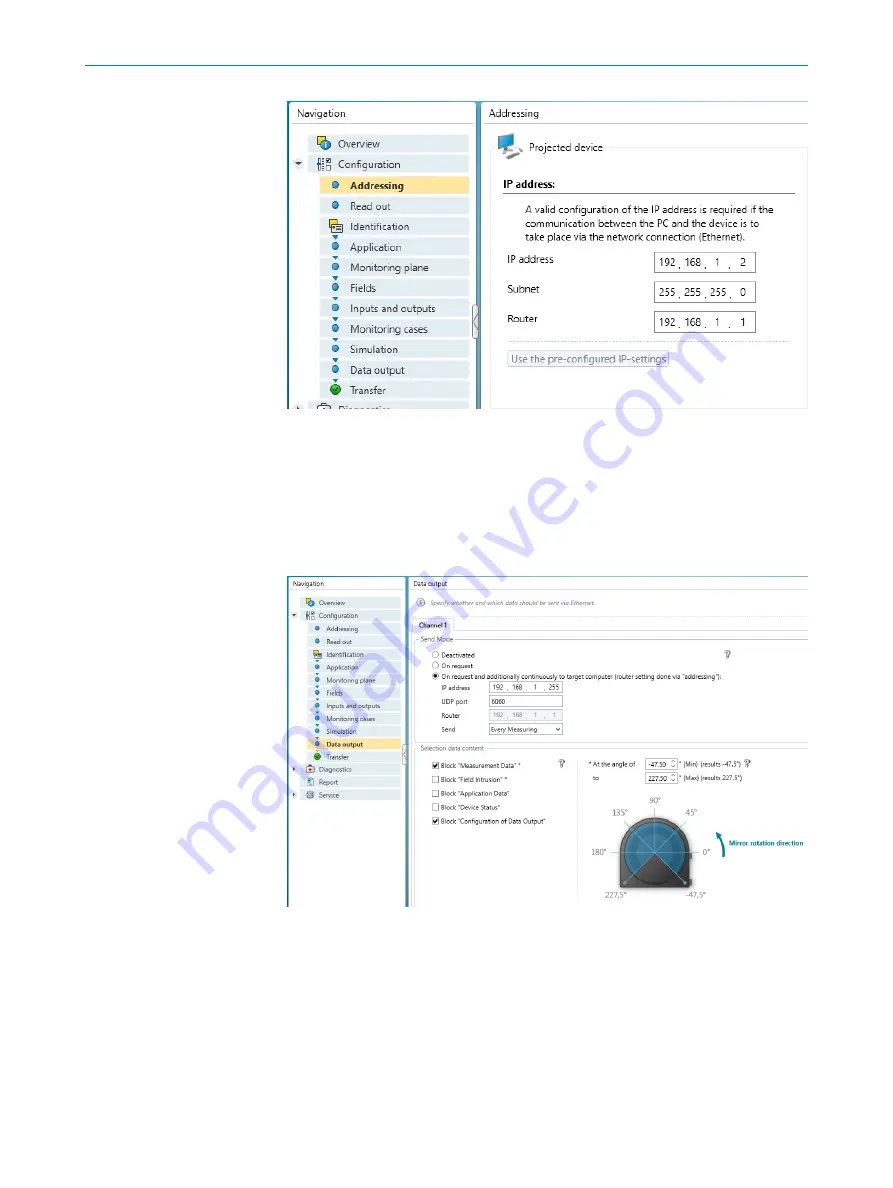
Figure 12: Setting the IP address with the SICK Safety Designer
3.
In
Data output
, choose
On request and additionally continuously
.
4.
In section
Send Mode
, enter the
IP address
of the target computer to the broadcast
UDP address, e.g. 192.168.1.255.
5.
Enter the
UDP port
, for example, 6060.
6.
In
Send
, select E
very Measuring
.
7.
In section
Selection data content
, select the information blocks
Measurement Data
and
Derived Values
.
Figure 13: Configuring the data output with the SICK Safety Designer
6
MICROSCAN3 CONFIGURATION OF THE DATA OUTPUT
20
T E C H N I C A L I N F O R M A T I O N | LiDAR Localization Hardware Integration
8024819/2019-09-02 | SICK
Subject to change without notice