


b
Read the operating instructions before using the Inspector.
b
Connection, assembly, and settings must be performed
by competent technicians.
b
Do not connect external I/O signals to the Inspector while
it is powered. This may damage the device.
b
Make sure that any loose cable ends are properly separated
or isolated before powering the Inspector. Otherwise the
device may be damaged.
b
Protect the Inspector from moisture and dirt during
operation.
b
Do not use the Inspector in areas with risk for explosion.
b
To keep IP 67 classification, open and close the front
window only with the supplied tool. Make sure that the seal
fits properly (Flex)
b
To avoid damages, only Inspector accessory lenses offered
by SICK are allowed to be used (Flex)
b
Minimize the risk of getting dust into the device by changing
the lenses in a dust-free environment. Do not keep the
device without the front window and wipe off the front
window before you open it (Flex)
2D vision
8013387/YUV5 ∙ Printed in Germany (2016-06)
All rights reserved. Subject to change without prior notice.
Q U I C K S TA R T
Inspector I10, I20, I40
Australia
Phone +61 3 9457 0600
1800 334 802 – tollfree
Austria
Phone +43 22 36 62 28 8-0
Belgium/Luxembourg
Phone +32 2 466 55 66
Brazil
Phone +55 11 3215-4900
Canada
Phone +1 905 771 14 44
Czech Republic
Phone +420 2 57 91 18 50
Chile
Phone +56 2 2274 7430
China
Phone +86 20 2882 3600
Denmark
Phone +45 45 82 64 00
Finland
Phone +358-9-2515 800
France
Phone +33 1 64 62 35 00
Germany
Phone +49 211 5301-301
Hong Kong
Phone +852 2153 6300
Hungary
Phone +36 1 371 2680
India
Phone +91 22 4033 8333
Israel
Phone +972 4 6881000
Italy
Phone +39 02 274341
Japan
Phone +81 3 5309 2112
Malaysia
Phone +6 03 8080 7425
Mexico
Phone +52 472 748 9451
Netherlands
Phone +31 30 2044 000
New Zealand
Phone +64 9 415 0459
0800 222 278 – tollfree
Norway
Phone +47 67 81 50 00
Poland
Phone +48 22 539 41 00
Romania
Phone +40 356 171 120
Russia
Phone +7 495 775 05 30
Singapore
Phone +65 6744 3732
Slovakia
Phone +421 482 901201
Slovenia
Phone +386 591 788 49
South Africa
Phone +27 11 472 3733
South Korea
Phone +82 2 786 6321
Spain
Phone +34 93 480 31 00
Sweden
Phone +46 10 110 10 00
Switzerland
Phone +41 41 619 29 39
Taiwan
Phone +886 2 2375-6288
Thailand
Phone +66 2645 0009
Turkey
Phone +90 216 528 50 00
United Arab Emirates
Phone +971 4 88 65 878
United Kingdom
Phone +44 1727 831121
USA
Phone +1 800 325 7425
Vietnam
Phone +84 945452999
Detailed addresses and additional
representatives and agencies
at
www.sick.com
Installing
Safety
Product Features
Teaching with SOPAS ET
Teaching without PC
Object Locator
Detailed Inspections
Overview
SOPAS ET
Pixel counter
Counts the number of pixels within the region that has an
intensity (grey scale value) that is within a specified range.
The location of these pixels is not considered, only the
number of pixels.
Edge pixel counter
Similar to the Pixel counter, but counts the number of
edge pixels in the region. The location of the edges is not
considered, only the number of pixels.
Contour
Compares the contours in the region with the contours in
the same region on the reference object. The better the two
contours correspond, the greater is the matching score for
the inspections.
Pattern (I40)
Compares each pixel’s value in the region with the
corresponding pixel value in the reference image. The better
the pixels correspond, the greater is the matching score for
the inspections.
<4 px
When teaching an Inspector which has not previously been
configured, the resulting reference object will have an object
locator that covers the entire field of view.
1. Place an object in front of the Inspector and connect in2
to +24 V.
After about 3 seconds the Function LED starts to flash.
3. Click Teach reference object.
The Inspector captures a reference image of the object
and displays it.
3. Find the field of view with the help of for example a pen.
When the Inspector detects movements in the field of
view, the Function LED changes color to blue.
5. Add detailed inspection over the parts of the object to be
inspected.
4. Disconnect in2 from the power.
The Inspector will now use the latest captured image as
reference image.
6. Test the inspection in the Live image and adjust the
settings if necessary.
5. The Inspector will then automatically switch to Run mode
and start inspecting
When the inspections are accurate enough, switch to Run to
put the Inspector in operation. When asked, you should save
the settings in the Inspector’s flash memory to assure that
they will be remembered if the power should be disconnected.
1. Mount the Inspector at an appropriate distance from the
objects to be inspected.
SOPAS ET is the PC application that is used for monitoring and
configuring the Inspector. It can be installed on any PC, and
then be used for accessing any Inspector that is connected to
the same network as the PC.
To connect to an Inspector from SOPAS ET.
1. Make sure that the Inspector is powered, and connected
to the PC or to the same network as the PC.
2. Start
SOPAS ET
.
3. In the
Device search
pane, double-click on the Inspector in
the list of available devices.
An object locator is used when teaching the Inspector to
recognise the objects to inspect. Each reference object can
not have more than one object locator.
The Inspector locates an object by recognising the contours
of it. The contours that are used are highlighted in green in
SOPAS ET.
b
Adjust the amount of contours to learn with the
Edge
strength
slider on the
Object locator
tab.
b
Adjust the size, location, shape, and rotation of the object
locator so that it covers the object properly. Use masks
to mask out areas that normally varies on the object, for
example if they have different labels .
OK
Enough amount
of learned
contours
Bad
Too few
contours
Bad
Too many con-
tours, as well as
contours on the
background
Match Settings
b
If objects are never rotated, deselect
Allow rotation
to
improve both robustness and speed.
b
To verify that objects are not rotated more than a small
amount, select
Allow rotation
and set the max rotation to a
small amount.
b
If objects are always of the same size and at the same
distance from the Inspector, deselect
Allow scaled objects
to
improve both robustness and speed.
An Inspector with ring
light
may need to be
mounted at a small angle
to avoid too much reflexes.
An Inspector with Dome
light
should be aligned
with the objects, at a
distance of approximately
50 mm to get optimal
effect of the dome lighting.
2. Connect the Ethernet connector on the Inspector to a
network, or directly to an Ethernet connector on a PC.
4. If necessary, adjust the size and location of the object
locator, and the amount of highlighted contours.
b
Bright contours are more important than dim contours.
b
Avoid highlighting contours outside the object.
b
It is not necessary to get bright contours everywhere on
the important contours.
Note
:
The Edge strength setting for Edge pixel
counter and Contour inspections is common
for all inspections of these types for a reference
object.
The Inspector
first locates the
object...
... and then inspects
details on the found
object.
Detailed
inspection
Object
locator
b
High-speed object inspection
b
Robust pattern match algorithm to locate objects indepen-
dent of position, rotation and scale
b
Multi-feature inspections /object
b
Multi-reference object teaching
b
Easy-to-use configuration in PC
b
Emulator, log, statistics and record for production control
b
Industrial Ethernet for monitoring over network
b
Exchangeable lens (Flex)
b
Outputs by logical expressions (I20, I40)
b
Input and output extensions via I/O box (I20, I40)
b
Store inspected images to remote FTP server (I40)
b
Provide detailed inspection results over EtherNet/IP (I40)
b
Live image/log/statistics view and reference object change
via external Viewer
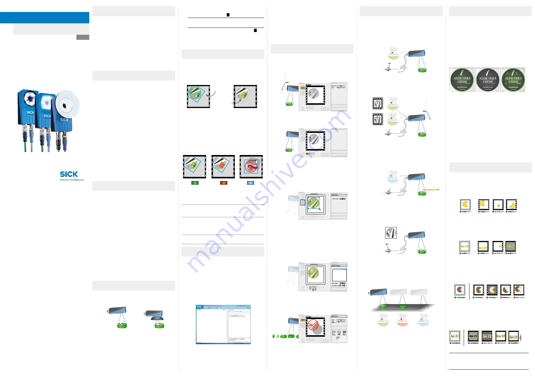
The Inspector inspects objects in the following way:
b
First, it locates the object in the view.
b
After that, it inspects details on the object to find out
whether the object is OK or not.
All passed
Detail failed
Not located
On
On
On
Off
Each inspection gives one of the following results:
Not located
The object was not located, or a detailed
inspection was out of view
Detail failed
The object was located but at least one of the
detailed inspections failed.
All passed
The object was located and all detailed inspec-
tions passed as well.
The Inspector provides the inspection result in the following
ways, depending on the model:
I10
3 fixed built-in digital
outputs
out1 – Not located
out2 – Detail failed
out3 – All passed
I20,
I40
3 built-in digital outputs
16 additional digital
outputs with I/O exten-
sion box
Configurable, using
Outputs by logical
expressions
(Default same as I10)
I40
EtherNet/IP
Detailed inspection
results
1. Switch the Inspector to Edit mode by clicking
Edit
in the
main view.
2. Place an object in front of the Inspector, and adjust focus
and exposure so that the Live image is sharp and bright.
2. Adjust focus by turning the focus screw.
The faster the Function LED flashes, the better the focus.
±4 px
The device now appears in the
New Project
pane. Double-click
on the device to open the device window and start the
configuration.
b
If the Inspector is not listed in the
Device search
pane, click
Search settings
to fine tune the search criteria.
b
If the connection to the device is not working, change the
IP settings of the device via the edit icon on the device tile.
Also make sure that the required SOPAS Device Driver (SDD)
is installed: Select the
Device catalog
tab and add the SDD via
the
Configuration
button.
For more information about the connection, see the online
help.
3. If the input or output signals are used, or if an external
lighting will be used, connect those devices to the
Inspector’s Power connector (
B
).
Note:
Make sure that the loose ends of the I/O cable
are separated before powering the Inspector.
4. Connect the Inspector to a 24 V DC power supply (
B
).
5. If a PC should be used for configuring the Inspector,
install the configuration software SOPAS ET v 3.x. SOPAS
ET is available for download, free of charge, from the
Software finder at www.sick.com.
SICK uses standard IP
technology for its products, e.g. IO Link,
industrial PCs. The focus here is on providing availability of
products and services.
S
ICK always assumes that the integrity and confidentiality of
data and rights involved in the use of the above-mentioned
products are ensured by customers themselves.
In all cases, the appropriate security measures, e.g. network
separation, firewalls, antivirus protection, patch management,
etc., are always implemented by customers themselves,
according to the situation.
Disclaimer
EN


