background image

°

A slave address that is free in the Modbus network

°

A slave address that the master expects

The same baud rate must be set in the GLS100 as in the master.

The following parameters are factory set on the GLS100:

Slave address: 10

Baud rate: 19,200 bps

Parity: Even

The following communication parameters can be allocated to the GLS100:

Slave address: 1 to 247 (0 is generally assigned to the master)

Baud rate:
0: 1,200 bps
1: 2,400 bps
2: 4800 bps

3: 19,200 bps

4: 19,200 bps
5: 38,400 bps
6: 57,600 bps
7: 115,200 bps

7.4.2

Basic information about Modbus and reading out code information

Modbus is based on RS-485 with a Modbus RTU protocol structure. Data exchange is
always based on requests from the master and responses from the slave devices. The
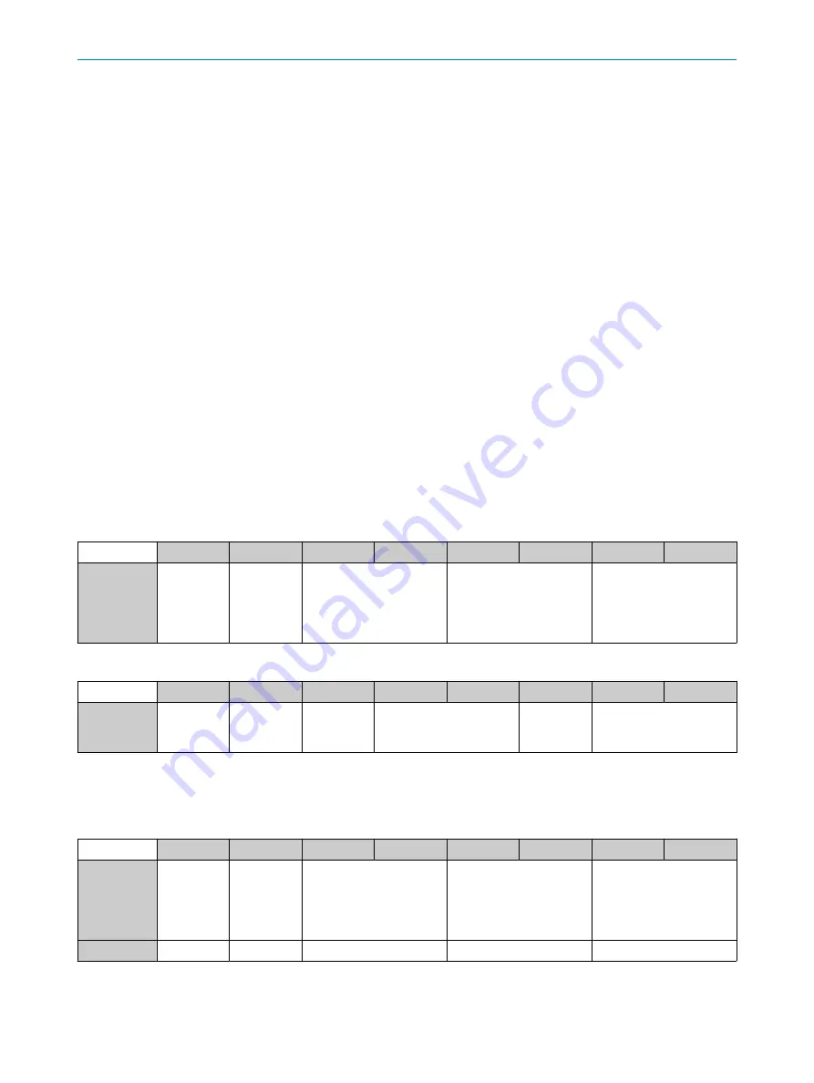
respective request/response string looks like this:

Request

Byte

0

1

2

3

4

5

6

7

ModBus con‐
tents

Slave
Address

“Function
code” e.g.
0x04 Read
“Input regis‐
ters”

Readout: Start address
(16 bit unsigned)

Readout: Number register
N (16 bit unsigned)

Checksum (16 bit
unsigned)

Response

Byte

0

1

2

3

4

2xN+5

2xN+6

2xN+7

ModBus con‐
tents

Slave
Address

Response:
“Function
code” 0x04

Number of
bytes, 2xN

Start register

Register
contents

Checksum (16 bit
unsigned)

The relevant code information is provided in “Section result data”. Read it out periodically (not more often than
every 50 ms) (addresses 320 to 331) using "Modbus function code #4":

Example

Byte

0

1

2

3

4

5

6

7

ModBus con‐
tents

Slave
Address

“Function
code” e.g.
0x04 Read
“Input regis‐
ters”

Readout: Start address
(16 bit unsigned)

Readout: Number of regis‐
ters (16 bit unsigned)

Checksum (16 bit
unsigned)

Value (hex)

0x0A

0x04

0x0140

0x000C

0xF15C

COMMISSIONING

28

O P E R A T I N G   I N S T R U C T I O N S | GLS100

8026282/2021-05-26 | SICK

Subject to change without notice

Summary of Contents for GLS100

Page 1: ...O P E R A T I N G I N S T R U C T I O N S GLS100 Grid localization...

Page 2: ...in the limits of the legal determination of Copyright Law Any modi fication abridgment or translation of this document is prohibited without the express written permission of SICK AG The trademarks st...

Page 3: ...4 1 Transport 17 4 2 Transport inspection 17 4 3 Storage 17 5 Mounting 18 5 1 Preparation for mounting 18 5 2 Mounting the sensor 18 6 Electrical installation 20 6 1 Safety 20 6 2 Pin assignment of t...

Page 4: ...10 Decommissioning 41 10 1 Decommissioning 41 11 Technical data 42 12 Accessories 44 13 Licenses 45 14 Annex 46 14 1 EU declaration of conformity 46 CONTENTS 4 O P E R A T I N G I N S T R U C T I O N...

Page 5: ...he machine in which the sensor is integrated For information about this refer to the operating instructions of the particular machine 1 2 Scope These operating instructions explain how to incorporate...

Page 6: ...vice variants containing technical data and dimensional drawings EU declaration of conformity for the product family Dimensional drawings and 3D CAD dimension models in various electronic for mats The...

Page 7: ...ecifically approved by SICK AG is at your own risk The sensor is not suitable for outdoor applications The sensor must not be operated with a long cable 30 m according to EN 61000 6 2 NOTICE Danger du...

Page 8: ...Electrician Other relevant regulations applicable in other countries must be observed The following qualifications are required for various activities Activities Qualification Mounting maintenance Ba...

Page 9: ...ized person nel from SICK AG Interruptions or modifications to the sensor on the part of the customer will invalidate any warranty claims against SICK AG SAFETY INFORMATION 2 8026282 2021 05 26 SICK O...

Page 10: ...4 5 3 Figure 1 Type label 1 Type designation 2 Part number 3 Machine readable code 4 Serial number 5 Pin assignment example for CAN device 3 PRODUCT DESCRIPTION 10 O P E R A T I N G I N S T R U C T I...

Page 11: ...1 26 53 6 2 11 4 2 0 17 24 0 94 1 2 3 Figure 2 Device view 1 Optical axis 2 Fixing hole 4 1 mm 3 M12 male connector rotatable by 180 130 6 5 14 98 3 86 1 Figure 3 Field of view 1 Field of view W x H...

Page 12: ...upply voltage on LED off No operation 3 2 Product features Function and use The GLS100 localizes automatic guided vehicle systems AGV systems using 2D codes The device is mounted on the underside of t...

Page 13: ...ng read data via the interface Status Code label position x y z Code label orientation as angle Code data Number of the MultiCode label Time stamp Overspeed in x and y direction PRODUCT DESCRIPTION 3...

Page 14: ...2 3 1 4 1 y direction Code coordinate system 2 y direction Sensor coordinate system 3 Field of view 160 mm x 120 mm 4 Coordinates in the sensor coordination system x y In addition it is possible for...

Page 15: ...rY Y angle X rX 1 2 3 4 1 y direction Code coordinate system 2 y direction Sensor coordinate system 3 Field of view 160 mm x 120 mm 4 Coordinates in the sensor coordination system x y PRODUCT DESCRIPT...

Page 16: ...ngle code only or Data Matrix MultiCode formats provided by the customer can be used QR single codes must correspond to the 21x21 25x25 29x29 33x33 or formats The maximum edge length must not exceed 3...

Page 17: ...ly do so conditionally Note the scope of damage on the transport documents or on the transport compa ny s delivery note File a complaint NOTE Complaints regarding defects should be filed as soon as th...

Page 18: ...supplied for this purpose there are no screw connections on the sensor Sensing distance 100 mm 30 mm The sensing distance is the distance from the front sensor edge housing edge to the ground 5 1 2 Sc...

Page 19: ...Table 4 Mounting Figure 6 Arrangement via code grid and traverse direction MOUNTING 5 8026282 2021 05 26 SICK O P E R A T I N G I N S T R U C T I O N S GLS100 19 Subject to change without notice...

Page 20: ...short circuit when supply voltage is switched on Wires must be appropriately insulated from each other Wire cross sections in the supply cable from the user s power system must be designed in accordan...

Page 21: ...rossed at right angles see figure 7 b Cables in groups 1 2 and 3 4 must be routed in different cable channels or metallic separators must be used see figure 8 and see figure 9 This applies particularl...

Page 22: ...per current standard EN 60950 1 Power source with at least 3 W power Protecting the supply cables To ensure protection against short circuits overload in the customer s supply cables the wire cross se...

Page 23: ...CANopen communication interface as a reference If there is no separate CAN GND in the system this pin is to be connected to the FE ELECTRICAL INSTALLATION 6 8026282 2021 05 26 SICK O P E R A T I N G...

Page 24: ...rk exchange data CANopen in the OSI model The CANopen protocol is a standardized Layer 7 protocol for the CAN bus This layer is based on the CAN Application Layer CAL 7 6 5 4 3 2 1 7 CAN application l...

Page 25: ...y PDOs emergency messages Stopped In this state the GLS100 is not actively communicating although communi cation is still being actively monitored via node guarding The GLS100 automatically enters the...

Page 26: ...configuration state LSS command result Slave is in configuration state transmit 7E5h 8 04 01 00 00 00 00 00 00 3 Send LSS command Configure Node ID to set the node ID to 19 transmit 7E5h 8 11 13 00 00...

Page 27: ...Os 1 to 3 are mapped as described under 8 1 2 7 3 5 PDO communication In the factory setting the transmission type for TPDO 01 TPDO02 and TPDO03 is set to asynchronous communication A transmission per...

Page 28: ...tring looks like this Request Byte 0 1 2 3 4 5 6 7 ModBus con tents Slave Address Function code e g 0x04 Read Input regis ters Readout Start address 16 bit unsigned Readout Number register N 16 bit un...

Page 29: ...8 bit unsigned 16 bit unsigned 16 bit unsigned 16 bit After the sensor response interpret the status in register 320 If bits 0 1 2 are set in the status all registers have been received and are valid...

Page 30: ...rror register 0x00 UINT8 0x1005 R W COB ID SYNC 0x000000 80 UINT32 0x1008 RO Manufacturer device name STRING GLSXXXX 0x1009 RO Manufacturer hardware rev STRING Hardware version sensor 0x100A RO Manufa...

Page 31: ...ID 0x000003 8A UINT32 PDO 3 is valid 2 R W Transmission type 0xFF UINT8 Asynchronous 3 R W Inhibit Time 0x0000 UINT16 5 R W Event timer 0x0032 UINT16 50 ms default 0x1803 Transmit PDO Communication P...

Page 32: ...y 5 0x000000 00 UINT32 6 R W Mapping Entry 6 0x000000 00 UINT32 7 R W Mapping Entry 7 0x000000 00 UINT32 8 R W Mapping Entry 8 0x000000 00 UINT32 0x1A02 0 R W Number of map ped objects 0x03 UINT8 1 R...

Page 33: ...tered 2 R W Code module size 1 0 FLOAT 1 0 mm default definition SICK MultiCode Tag 3 R W Distance to inner code 0 009 FLOAT 0 009 m default for 1mm pixel size in SICK Multi Code Tag 4 R W Distance to...

Page 34: ...is a multiple of 1 m xz 5 RO Angle INT16 x Code orientation Positive values in clockwise direction For output value see scaling Multiple of 1 phis 6 RO Tag Id UINT32 x Numeric read value of code tag 3...

Page 35: ...e Permissible values Description 1 COB ID The COB ID is automatically adjusted to the note ID and should not be amended by the user 2 Transmission type 0 255 The transmission type is set here 3 Inhibi...

Page 36: ...ck com 20 Product name 16 36 Model name 9 45 Serial number 4 49 Application name 16 65 SickModBusProfileVersion 6 Result section The Section Index registers contain the results of the read code Addres...

Page 37: ...Address Name Register Description Value 96 Set Application name 16 To be set Configuration section NOTE Changes become active only after a power cycle Address Name Register Description Value 144 Modbu...

Page 38: ...es 320 to 331 periodically not more often than every 30 ms Use Modbus function code 0x04 If status bits 0 1 2 are set all registers are valid The time offset value register address 329 can be used to...

Page 39: ...e as a 16 bit integer value To output the angle directly in integer degrees set phis to the value 180 pi 57 3 The angle format configuration parameter can be used to switch between a signed pi pi 180...

Page 40: ...s 9 2 Maintenance The sensor requires the following maintenance work at regular intervals Table 11 Maintenance schedule Interval Maintenance work To be performed by Cleaning interval depends on ambien...

Page 41: ...move the sensor from the slot Disposing of the sensor Any sensor which can no longer be used must be disposed of in an environmentally friendly manner in accordance with the applicable country specifi...

Page 42: ...r and after sensor warm up phase 4 In nominal sensing range 100 mm when using the SICK MultiCode label Mechanics electronics Table 13 Mechanics electronics 1116319 1114008 Connection type 1 x M12 5 pi...

Page 43: ...ervice life 100 000 h at TU 25 C Ambient data Table 16 Ambient data 1116319 1114008 Electromagnetic compatibility EMC EN 61000 6 3 2007 A1 2011 IEC 61000 6 3 2006 AMD1 2010 EN 61000 6 2 2005 08 Vibrat...

Page 44: ...Accessories can be found on the online product page at www sick com 1114008 www sick com 1116319 12 ACCESSORIES 44 O P E R A T I N G I N S T R U C T I O N S GLS100 8026282 2021 05 26 SICK Subject to c...

Page 45: ...e This program is provided for general use but WITHOUT ANY WARRANTY OF ANY KIND This warranty disclaimer also extends to the implicit assurance of marketability or suitability of the program for a par...

Page 46: ...rmity The EU declaration of conformity can be downloaded from the Internet at www sick com 1114008 www sick com 1116319 14 ANNEX 46 O P E R A T I N G I N S T R U C T I O N S GLS100 8026282 2021 05 26...

Page 47: ...ANNEX 14 8026282 2021 05 26 SICK O P E R A T I N G I N S T R U C T I O N S GLS100 47 Subject to change without notice...

Page 48: ...8080 7425 E Mail enquiry my sick com Mexico Phone 52 472 748 9451 E Mail mexico sick com Netherlands Phone 31 0 30 229 25 44 E Mail info sick nl New Zealand Phone 64 9 415 0459 0800 222 278 tollfree...

Reviews: