28
8026957/AE00/V1-0/2021-08| SICK
O P E R A T I N G I N S T R U C T I O N S | DUSTHUNTER SB30
Subject to change without notice
3
ASSEMBLY AND INSTALLATION
2
Electrical connection
▸
Compare power voltage and frequency with the specifications on the type plate on the
purge air motor.
▸
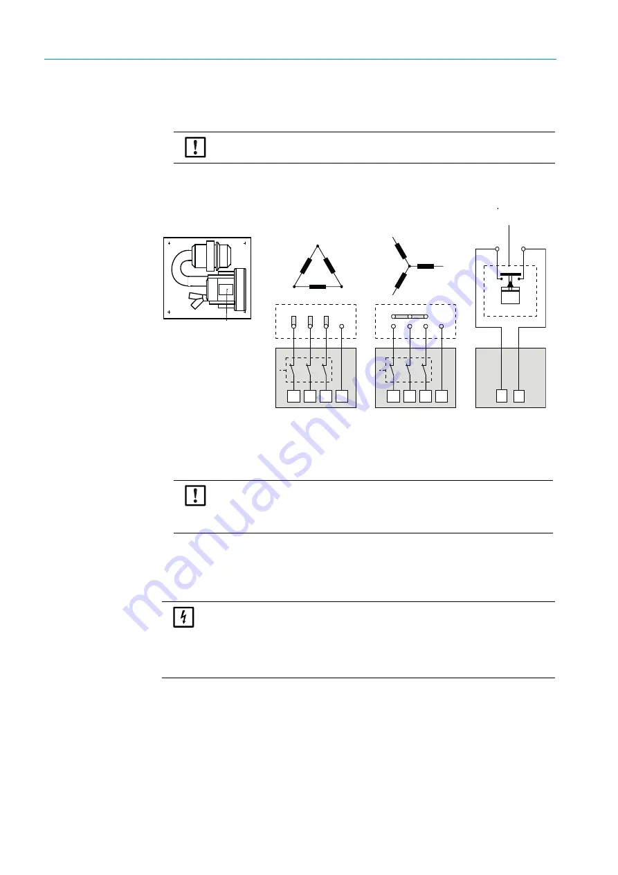
Connect the power supply line to the purge air motor terminals (refer to the
supplementary sheet on the purge air motor and lid of the motor terminal box for
terminal allocation).
Fig. 14: Electrical connection of the external purge air unit
▸
Connect protective conductor to terminal.
▸
Set motor circuit breakers according to the blower connection data (see Technical Data
for purge air unit) to a value 10% above the rated current.
▸
Check the function and running direction of the blower (purge air flow direction must
match the arrows on the inlet and outlet openings on the blower). For wrong direction on
3-phase motors: Swap power connections L1 and L2.
▸
Connect the pressure controller (option) to monitor purge air feed.
CAUTION:
▸
Only connect when these match!
L1
L1
U1
U1
U1
U1
V1
V1
V1
V1
W1
W1
W1
W1
PE
PE
W2
W2
W2
W2
V2
V2
V2
V2
U2
U2
U2
U2
L2
L2
+
24 V
L3
L3
_
PE
PE
Low-pressure monitor
Energy supply
4 x 1.5 mm²
NOTE:
In case of doubt or when using a special motor version, the operating
instructions supplied with the motor have priority over any other
information.
NOTE:
▸
Use a fail-safe power supply (standby unit, rails with redundant supply).
▸
Fuse the purge air unit separate from the other system components. The
fuse type must match the rated current (see technical details of purge air
unit). Fuse each phase separately.
Use circuit breakers to prevent phase failures on one side.


