YQE8-J0093E
6
Maintenance Parts Replacement Procedures
1
/
1
Parts
Name
PCB HSSV7-LCDSOSA-F ASSY
Part No.
164-11-09757
Tools
Phillips Screwdriver (#2)
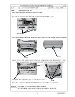
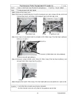
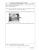
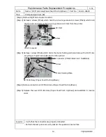
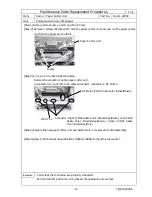
[Step 1] Remove Side Covers L and R and Front Cover.
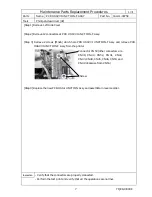
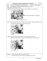
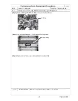
[Step 2] Remove two white collars which cover buttons of PCB HSSV7-LCDSOSA-F Assy.
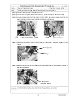
[Step 3] Remove the connector (CN21) at PCB HSSV7-LCDSOSA-F Assy, remove 2 screws (M3x6)
which hold the PCB, then remove PCB HSSV7-LCDSOSA-F Assy from the printer.
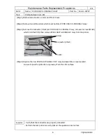
[Step 4] Replace the new PCB HSSV7-SOSALCD-F Assy and assemble in reverse order.
Be sure to peel the protective vinyl away from the LCD surface.
Inspection
- Verify that the connectors are properly connected.
- Perform the test print and verify that all the operations are normal.
Connector (CN21)
Collar
Screw


