YQE8-J0093E
33
Maintenance Parts Replacement Procedures
2
/
3
Parts
Name
Pinch Roller Sensor Assy
Part No.
164-11-09762
Tools
Phillips Screwdriver (#2), Phillips Screwdriver (#2, longer than 300mm), Phillips
Screwdriver (#2, shorter than 100mm), Flat-blade Screwdriver (2.5x100), Pliers
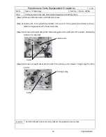
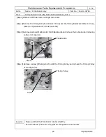
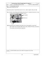
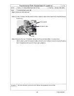
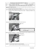
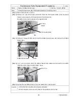
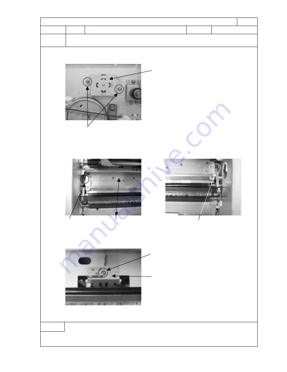
[Step 6] Remove 2 screws (M3x6) which hold the Ribbon Core Holder Assy and remove the Ribbon
Core Holder Assy from the printer.
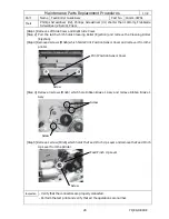
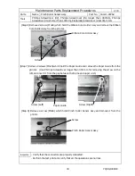
[Step 7] Remove 2 screws (M3x6) which hold the Paper Guide and remove the Paper Guide from the
printer. (Use Phillips Screwdriver longer than 300 mm for removing the screw on the
left, and insert it from the gap between the frame and upper unit.)
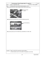
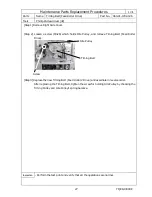
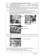
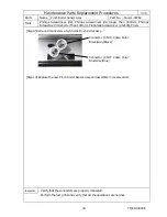
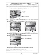
[Step 8] Remove a screw (M3x6) which holds Pinch Roller Sensor Assy and remove it from the
printer.
Inspection
- Verify that the connectors are properly connected.
- Perform the test print and verify that all the operations are normal.
Screw (Left)
Paper Guide
Screw
Pinch Roller Sensor Assy
Screw (Right)
Screw
Ribbon Core Holder Assy

