


40(83)
Ø
Wizard Mode (teach mode): teach and save the sequences of program actions.
Ø
Servo Setup: setup each servo axis parameters.
Ø
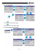
Port Monitor: monitor each input/output signal.
Ø
System Setup: setup system parameters.
Ø
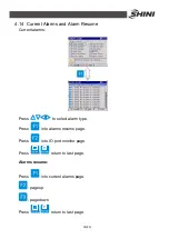
Alarm Resume: show recent 30 records system alarm.
Ø
Adjust Motor: adjustment mechanical limit of robot.
Ø
System Inf. (information): show system information: robot model, version, manufacturer
and so on.
4.8 Program File Management
4.8.1 Program File Explorer
Program is stored and managed as a file. Each file has a unique ID, for example,
P01. The files also have name, the length of one name string is 9 characters at
most. If the program has no file name, means it is a null program.
When select current program or select program in teach mode, the program
explorer will be open automatically. Select current program in manual mode, or
select program in teach mode to enter
“
program explorer
”
page. Rename, copy
or delete files.
Use
to select program file.
: copy file.
: delete file.
: rename file.
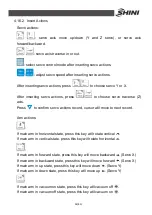
4.8.2 Program Rename
Press
“
F3
”
to rename file, the
“
string editor
”
will display on screen.
Use
to input word.
: shift word capitalization and lowercase.
Summary of Contents for ST2
Page 2: ......
Page 8: ...8 83 ...
Page 31: ...31 83 4 Operating Instruction 4 1 Hand Controller 4 1 1 Operation Panel of Hand Controller ...
Page 63: ...63 83 7 Assembly Diagram 7 1 Traverse Unit Picture 7 1 Traverse Unit ...
Page 65: ...65 83 7 3 Main Arm Unit Picture 7 2 Main Arm Unit ...
Page 67: ...67 83 7 5 Crosswise Unit Picture 7 3 Crosswise Unit ...
Page 76: ...76 83 8 8 Z axis I O Board Wiring Diagram Picture 8 8 Z axis I O Board Wiring Diagram ...
Page 77: ...77 83 8 9 Main Arm Wiring Diagram 1 Picture 8 9 Main Arm Wiring Diagram 1 ...
Page 78: ...78 83 8 10 Main Arm Wiring Diagram 2 Picture 8 10 Main Arm Wiring Diagram 2 ...
Page 79: ...79 83 8 11 Sub arm Wiring Diagram Picture 8 11 Sub arm Wiring Diagram ...
Page 83: ...83 83 8 15 Pneumatic Schematic Diagram Picture 8 15 Pneumatic Schematic Diagram ...


