background image


49(77) 


3.  Installation and Debugging 


Please read carefully this part before installation.


Please install the machine according to the following orders in order to 

avoid human injury and machine damage! 

  Please be very careful and avoid cut by the extremely sharp blades! 


Power  connection  of  granulator  must  be  accomplished  by  professional 

electricians!   

Table 3-1: Torque Forces of Blades and Other Fixing Screws 

Screw thread size 

M10 

M12 

M14 

M16 

M18 

M20 

M22 

M24 

Axial force (N) 

23.8  34.5 

47 

65.5  78.5 

103 

129 

149 

Tightening torque force (Nm) 

50 

86 

135 

215 

290 

420 

570 

730 

3.1  Installation Notices 

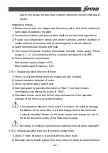
1) Please ensure that the voltage and frequency match with those marked on         

name plate provided by the plant. 

2) Connection of cables and ground wires shall accord with local regulations. 
3) Please use independent cables and power switches and the diameter of 

cables shall not be less than that of cables applied in electric cabinet.   

4) Cable terminals shall be safe and fixed. 
5) This series of machine requires three-phase four-wire power supply. Power 

supply (L1, L2, L3) connects with live conductor and ground wire (PE). 

6) Power distribution requirement: 

Main power supply pressure: 

±

 10% 

Main power supply frequency: 

±

 2% 

3.2  Installation Positions 


Please use correct lifting method! 

Feed  box  and  granulator  body  are  separately  packaged  when  the 

machine leaves the factory. Use forklift to move the granulator body to 

Summary of Contents for SGS-6080S

Page 1: ...SGS S Single shaft Shredders Date May 2014 Version Ver B English...

Page 2: ......

Page 3: ...d Working Principle 19 2 1 General Description 19 2 1 1 Working Principle 19 2 2 Security System 20 2 2 1 Emergency Switch 21 2 2 2 Safety Switch 21 2 3 Assembly Drawing 23 2 3 1 Assembly Drawing 23 2...

Page 4: ...of Main Cutter Shaft and Bearing 52 3 6 Installation of Pulley Motor and Reduction Gear 52 3 7 Installation of Blades 54 3 8 Installation of Screen and Frame 54 3 9 Connection of Hydraulic System 55 3...

Page 5: ...ntenance 69 6 1 1 Replacement of Blades 69 6 2 Transmission 71 6 2 1 Maintenance for V belt 71 6 2 2 Adjustment of V belt 72 6 3 Lubrication 72 6 3 1 Bearing lubrication oil Recommended brand 72 6 3 2...

Page 6: ...SGS 6080S Electrical Components List 42 Table 2 10 Conveyor Belt Parts List Matching in SGS 6080S 47 Table 3 1 Torque Forces of Blades and Other Fixing Screws 49 Picture Index Picture 1 1 Dimensions...

Page 7: ...allation of Shield 51 Picture 3 4 Installation of Main Cutter Shaft and Bearing 52 Picture 3 5 Installation of Main Cutter Shaft and Bearing 1 52 Picture 3 6 Installation of Main Cutter Shaft and Bear...

Page 8: ...8 77...

Page 9: ...from being cut which requires users to pay attention to them No treating with poisonous and inflammable materials SGS S series of single shaft shredders can shred extremely thick tough and large solid...

Page 10: ...surface to reduce the friction heat When one of the angles of cutter is broken it can simply inter change the cutter to improve cutting efficiency 4 Automatically hydraulic device can be adjusted to...

Page 11: ...Any modifications of the machine must be approved by SHINI in order to avoid personal injury and damage to machine We shall not be liable for any damage caused by unauthorized change of the machine Ou...

Page 12: ...ind conveying device Dimensions H mm 2300 2560 H1 mm 2455 2715 H2 mm 610 770 W mm 390 440 W1 mm 2040 2410 D mm 1780 2265 D1 mm 1060 1460 D2 mm 800 1200 D3 mm 800 1200 Weight kg 3970 5500 Note 1 stands...

Page 13: ...Labels Electrical installation must only be done by a competent electrician Disconnect main switch and control switch before the granulator servicing and maintenance Never put any part of your body th...

Page 14: ...ds and powders the temperature of material should be higher than 60 When replace and inspect conveying belts make sure disconnect main power and avoid objects or clothes to be nipped into belts Also m...

Page 15: ...e off or open shield during running Warning There is a pinch risk for this protective cover keep some distance away from that Warning The cutter are very sharp can cause injury take out or open protec...

Page 16: ...Machine structure is well balanced with transfer hoisting rings and please be careful while lifting the machine in order to avoid machine s falling down 5 Temperature requirement for the preservation...

Page 17: ...rk area No using this machine in following situations 1 Damaged cables 2 No running the machine on wet floors or after the machine is caught in the rain in order to avoid electric shock 3 Before the i...

Page 18: ...is exempted from liability for any costs fees claims and losses caused by reasons below 1 Any careless or man made installations operation and maintenances upon machines without referring to the Manu...

Page 19: ...ure 2 1 Working Principle Wastes fall into crushing chamber through feed hopper A Activated by hydraulic system oil cylinder drives pushing block to move wastes close to cutter shaft G Cutter shaft is...

Page 20: ...ug machine 2 2 Security System In order to prevent from accidental human injury during the operation the granulator is equipped with highly secured protection system Nobody is allowed to make any chan...

Page 21: ...ow direction which will reset the button counterclockwise direction Picture 2 4 Emergency Switch 2 2 2 Safety Switch Shredder is equipped with breaker with safety switch which cuts power if hopper pos...

Page 22: ...screen open to ensure operation safety Picture 2 5 Screen Frame Safety Switch Notice before start up 1 Check if screen frame and hopper are locked tightly 2 Check if motor baffle is well installed 3...

Page 23: ...Base dynamic drawing 3 Support arm buffer assembly drawing 4 Cutting chamber assembly drawing 5 Pushing mechanism 6 Pushing block shield 7 Right connecting rod 8 Connecting rod fixed flange BH1108045...

Page 24: ...24 77 2 3 3 Cutting Chamber Structure Picture 2 8 Cutting Chamber Structure...

Page 25: ...on loop BH10801320010 BW31751201810 15 Tool rest BH10801200210 BH10751200110 16 Inner hex screw M12x45 YW61124500000 YW61166000000 17 Flat washer 12x24 YW66122400000 YW65016000000 18 Inner hex screw M...

Page 26: ...0 YW61250000000 YW61250000000 40 Upper left fixed blade YW43801210000 BW31751201310 41 Upper right fixed blade YW43801010000 BW31751201410 42 Lower fixed blade pressing block BH11801210010 BL537512004...

Page 27: ...Parts List Table 2 3 Blades Assembly Parts List Number No Name SGS 6080S SGS 75120S 1 Main shaft BH10801200210 BH10751200110 2 Rotate blade fixed block BH11801290010 BH11751200410 3 Rotate blade YW43...

Page 28: ...330040000 YW30280800000 5 Taper sleeve 3535 60 YW30353506000 YW30353500000 6 Motor 37kW 225S 1LG4220 4AA60 400V 50Hz YM10000107300 YM10000107500 7 Inner hex screw M12x100 YW61121000000 YW61121000000 8...

Page 29: ...crew M10x25 YW61102500000 YW61102500000 17 Hex nut M10 YW64001000100 YW64001000100 18 Flat washer 10x24 YW66102500000 YW66102500000 19 Pulley cover support seat 2 3 9 Screen Table 2 5 Screen Parts Lis...

Page 30: ...3 11 Screen Frame Parts List Table 2 6 Screen Frame Parts List Number No Name SGS 6080S SGS 75120S 1 Screen frame fixed block BH10801560010 BH10801560010 2 Screen frame 3 Screen BL53801210020 BL53751...

Page 31: ...31 77 2 3 12 Pushing Device Assembly Picture 2 12 Pushing Device Assembly...

Page 32: ...hamber base plate 13 Cutting chamber welding drawing 14 Connecting hinge pin BH11080080040 BH11080080040 15 Bolt lock check ring BH11080090040 BH11080090040 16 Flat washer 30x56 YW66305400000 YW663054...

Page 33: ...ut loading condition operate device for 2 hours If you find uneven sounds overheat and oil leakage please shut it down and contact Shini Company During installing torque arm make point of connection b...

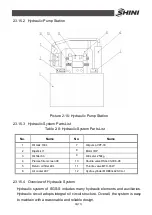
Page 34: ...34 77 2 3 15 Hydraulic System 2 3 15 1 Principle of Hydraulic System Picture 2 14 Principle of Hydraulic System...

Page 35: ...iller 63 9 Oil meter 250kg 4 Precise filter screen 08 10 Shuttle valve DSG 03 3C6 A5 5 Return oil filter 40L 11 Throttle valve MTC 03W 6 Air cooler 407 12 Hydro cylinder MOB63x420 CA I 2 3 15 4 Overvi...

Page 36: ...using Inspect if adjusting handle of elements and auxiliaries is in correct position if oil level in liquid indicator range if pipe joint and fastening screw are lose if valve and pipeline leaks 2 Ins...

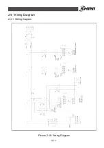
Page 37: ...37 77 2 4 Wiring Diagram 2 4 1 Wiring Diagram Picture 2 16 Wiring Diagram...

Page 38: ...38 77 2 4 2 Control Wiring Diagram Picture 2 17 Control Wiring Diagram 1...

Page 39: ...39 77 Picture 2 18 Control Wiring Diagram 2...

Page 40: ...40 77 2 4 3 Electrical Components Layout Picture 2 19 Electrical Components Layout 1...

Page 41: ...41 77 Picture 2 20 Electrical Components Layout 2...

Page 42: ...40 57A 11 F2 Thermal overload relay 6 3 10A YE01631000000 12 F3 Thermal overload relay 0 4 0 63A YE01046300000 13 F4 Fuse 2A YE41001000000 14 F5 Fuse base 32A 2P YE41032200000 15 Fuse core 2A YE460020...

Page 43: ...2A YE61250000000 41 X6 Heavy duty joint 16P YE68161600000 42 X7 Water joint 400V 16A YE63314100000 43 Water joint 400V 16A YE63314100000 44 M1 Granulating motor 400V 50Hz 37kW 45 M2 Pump motor 400V 50...

Page 44: ...al Overload Relay Picture 2 21 Main Electric Components 1 Thermal overload relay protects motor when overload or loss of phase 2 Electromagnetic contactor can connect or disconnect circuit in the dist...

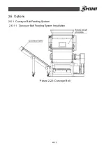
Page 45: ...45 77 2 6 Options 2 6 1 Conveyor Belt Feeding System 2 6 1 1 Conveyor Belt Feeding System Installation Picture 2 22 Conveyor Belt...

Page 46: ...46 77 2 6 1 2 Conveyor Belt Assembly Drawing CB 3675 Note Please refer to 2 6 1 3 material list about the parts code Picture 2 23 Conveyor Belt Assembly Drawing CB 3675...

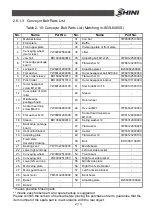
Page 47: ...cap screw M6 40 YW61064000000 44 Hex nut M27 YW64002700000 15 Flat washer 6 12 YW66061200000 45 Socket head cap screw M12 40 YW61124000000 16 Sleeve BH10062600010 46 Spring washer 12 YW65012000000 17...

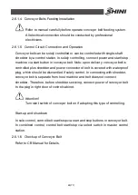
Page 48: ...olled plus shredder and power connector of belt is covered with waterproof plug which should be dismantled if solely control In connecting with shredder conveyor belt is separate from host machine and...

Page 49: ...ase ensure that the voltage and frequency match with those marked on name plate provided by the plant 2 Connection of cables and ground wires shall accord with local regulations 3 Please use independe...

Page 50: ...alling the feed box on granulator body and overweight will damage the machine Picture 3 1 Installation Positions Please assure of enough installation space in peripheral area of the machine for the co...

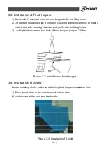
Page 51: ...with crushing chamber and justify with its fixing holes 3 Lock tightly the external hex bolts of feed hopper torque 220Nm Picture 3 2 Installation of Feed Hopper 3 4 Installation of Shield Before ins...

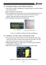
Page 52: ...Mount bearing end cap and lock it up with bolts Picture 3 4 Installation of Main Cutter Shaft and Bearing 3 6 Installation of Pulley Motor and Reduction Gear 1 Put key into keyway of cutter shaft use...

Page 53: ...taper sleeve into pulley round hole match hole sites with pulley and screw inner hex bolts M10mm 25 torque 45 Nm 9 Place motor on fixing plate and push it forward to shorten distances between pulley...

Page 54: ...inspect gap between fixed blades and rotate blades Normal range is 0 5 1 5mm if not change the gap by adjusting fixed blades then tighten fixing screw of fixed blades Picture 3 8 Installation of Fixed...

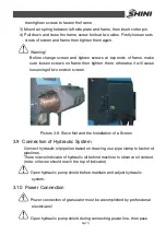
Page 55: ...l cause loosening of two ends in screen Picture 3 9 Sieve Net and the Installation of a Screen 3 9 Connection of Hydraulic System Connect hydraulic oil pipeline based on drawing use pipe clamp to fast...

Page 56: ...tion direction of motor 1 Check up if screen frame and feed hopper are well installed 2 Inspect operation direction of motor 3 Check up if emergency switch acts 4 Start granulator by pressing the butt...

Page 57: ...not operation normally At the same time it will also largely reduce the machine s crushing capability Please cut off power supply and change any two of the three connection wires of the main power su...

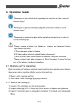
Page 58: ...sh rotators and blades to examine if they are loosened Please contact local sale company or Shini Company if users find out any of the above mentioned situations 4 1 Starting up Pre inspection Rust pr...

Page 59: ...motor rotate clockwise 4 2 1 Inspect the Operation Direction of Motor 1 Confirm main power switch is ON 2 Check up if emergency switch acts 3 Start shredder by pressing the button of Start then shut i...

Page 60: ...Use an object to support frame if manually working under screen to prevent injuries caused by spring bar failure 4 4 Close Screen Frame Attention Hold the handles on frame tightly and push them towar...

Page 61: ...controlling pushing block and cutter shaft Under Manual mode motor switch controls shaft running and reversely running turn on oil pump to control pushing block movements Attention Under Auto mode oi...

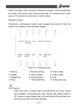
Page 62: ...is button if any accident or other situations happen Picture 4 3 Emergency stop 1 Running 2 Reverse running 3 Pump running 4 Feeding 5 Motor overload 6 Ampere meter 7 Manual Auto 8 Feeding return 9 St...

Page 63: ...tartup and first feeding After startup swing arm stays in top and time remained until first feeding default is 10S B7 Rejected material time remained Time remained when swing arm returns to the top de...

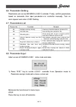
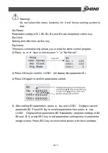
Page 64: ...2 Press or keys to move cursor to Set Param 3 Press OK key to confirm LOGO will display first parameter B1 4 Press OK again to confirm parameters edited 5 After setting B1 parameters press key and LOG...

Page 65: ...ssure exceeds 10MPA hydraulic motor will be overload Motor overload will make shredder fail to start Check the motor protector inside control cabinet protector shuts down when switch in 0 position Adj...

Page 66: ...ys idle 1 Inspect if oil pressure gauge is turned on 2 Inspect setting pressure of relief valve is too low if flow rate of one way throttle valve is too small or in shutdown 3 Inspect if oil circuit i...

Page 67: ...manually start machine and start oil pump motor Manually control pushing block to move backward and forward if machine starts then shift it to the Auto mode and running 3 If solutions above do not wor...

Page 68: ...rial pushing device Period Weekly 8 Check whether the anti vibration device is lossened if yes tighten the screw nut on it 9 Check the condition of the belt and belt tension Period Weekly 10 Check the...

Page 69: ...ration and please be very careful during operation to avoid cut injury Refer to chapter 3 4 for assembly during blades maintenance and replace After fix screws use thread fixing agents Blue LOCTITE234...

Page 70: ...hamber before demount them 2 Unscrew adjusting bolts of upper fixed blades 3 Take off bolts and fixed blades Caution When unscrew the lasting bolt make sure press pushing block and blades to avoid inj...

Page 71: ...n and running state after 20 30 full load operation Also check cog belt wear condition once in a month 2 Inspect cog belt tension every six month Open side plate of control cabinet rotate cog belt for...

Page 72: ...or plate A 2 Use four flexible bolts B and then adjust belt tension by changing gap between pulleys 3 Tighten flexible bolts B 4 Tighten fixed bolts C Recheck belt tension after 20 30 hours machine fu...

Page 73: ...unnel fill in with 10L gear lubricate oil VG460 If shredder not used for a long time apply oil to tool rest fixed blade rotate blade crushing chamber and screws Picture 6 3 Oil Filling and Drain of Re...

Page 74: ...is normal and stop the machine immediately after turn on the machine Rotate the button along the arrow direction namely counterclockwise direction to reset it 6 4 2 Weekly Inspection 1 Inspect if pow...

Page 75: ...and it would not drop down Watch out during working to avoid air spring sudden failure causing personal injuries 5 Clean interior of crushing chamber and residuals on blades 6 Dismantle storage hopper...

Page 76: ...hine Model SN Manufacture date Voltage V Frequency Hz Power kW 6 6 2 Check After Installation Check if pipe connections are firmed locked by clips Check the gap between fixed blade and rotating blade...

Page 77: ...d and rotate blades are under looseness Check if there is abnormal noise vibration and heat in reduction gear Check the cracking window 6 6 5 Monthly Check Inspect status of motor and reduction gear I...

Reviews: