32(77)
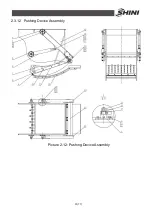
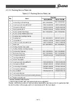
2.3.13 Pushing Device Parts List
Table 2-7: Pushing Device Parts List
Part No.
No.
Name
SGS-6080S
SGS-75120S
1
Connecting rod fixed flange
BH11080450040
BH11080450040
2
Inner hex round screw M12x40*
YW61124000000
YW61124000000
3
Flat washer
Ø
12x24*
YW66122400000
YW66122400000
4
Spring washer
Ø
12*
YW65012000000
YW65012000000
5
Hydro-cylinder fixed flange
BH11080020040
BH11080020040
6
Hydro-cylinder* MOB63x420-CA-I
-
-
7
Pushing block welding drawing
-
-
8
Pushing bar*
BH10080050010
BR90751200010
9
Locknut M12*
YW64101100000
YW64101100000
10
Inner hex round screw M10x35*
YW61103500000
YW61103500000
11
Gibb lock*
BH10080060010
BH10080060010
12
Cutting chamber base plate
-
-
13
Cutting chamber welding drawing
-
-
14
Connecting hinge pin
BH11080080040
BH11080080040
15
Bolt lock check ring
BH11080090040
BH11080090040
16
Flat washer
Ø
30x56*
YW66305400000
YW66305400000
17
Tacking bolt M8x12*
-
-
18
Sensor fixed plate
-
-
19
Inner hex round screw M5x25*
YW61052500200
YW61052500200
20
Flat washer
Ø
5x56*
YW66051000000
YW66051000000
21
Connecting rod bearing*
YW33801200000
YW33801200000
22
Flat washer
Ø
24x44*
YW66024400000
YW66024400000
23
Hex nut M24*
YW64002400100
YW64002400100
24
Left connecting rod
-
-
25
Connecting rod erection fixture welding drawing
-
-
26
Right connecting rod
-
-
* means possible broken parts.
** means easy broken part. and spare backup is suggested.
Please confirm the version of manual before placing the purchase order to guarantee that
the item number of the spare part is in accordance with the real object.
Summary of Contents for SGS-6080S
Page 1: ...SGS S Single shaft Shredders Date May 2014 Version Ver B English...
Page 2: ......
Page 8: ...8 77...
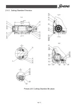
Page 24: ...24 77 2 3 3 Cutting Chamber Structure Picture 2 8 Cutting Chamber Structure...
Page 31: ...31 77 2 3 12 Pushing Device Assembly Picture 2 12 Pushing Device Assembly...
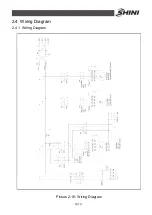
Page 37: ...37 77 2 4 Wiring Diagram 2 4 1 Wiring Diagram Picture 2 16 Wiring Diagram...
Page 38: ...38 77 2 4 2 Control Wiring Diagram Picture 2 17 Control Wiring Diagram 1...
Page 39: ...39 77 Picture 2 18 Control Wiring Diagram 2...
Page 40: ...40 77 2 4 3 Electrical Components Layout Picture 2 19 Electrical Components Layout 1...
Page 41: ...41 77 Picture 2 20 Electrical Components Layout 2...

