Table of Figures
VI Rack Modular UPS System 10-90kVA User Manual
Table of Figures
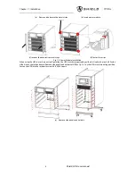
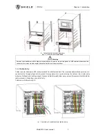
Fig.1- 2: Power Module Installation
..........................................................................................
Fig.1- 3: rack mounted installation
............................................................................................
...................................................................................................
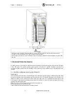
Fig.1- 6: Bypass Module (include bypass and monitoring)
..................................................
Fig.1- 7: Diagram of J2 and J3 Dry Contactor of Temperature Detection
Fig.1- 8: Diagram of Input Dry Contactor for Remote EPO
.................................................
Fig.1- 9: Connection of Generator
...........................................................................................
Fig.1- 11: Battery Low Warning Dry Contactor
.....................................................................
Fig.1- 12: Integrated warning dry contactor
..........................................................................
Fig.1- 13: Utility Failure Warning Dry Contactor
...................................................................
Fig.2- 1: Diagram of Batteries Connection
............................................................................
No table of figures entries found.
Fig.3- 1: Circuit diagram of EPO
...............................................................................................
Fig.3- 3: Connection of Parallel Cables of "1+N" System
....................................................
Fig.4- 2: External Battery Connection
....................................................................................
Fig.4- 3: 90kVA UPS module System, Front View and Rear View without Door
Fig.4- 4: 40KVA UPS Module System, Front View and Rear View without Door
Fig.4- 5: 20KVA UPS Module System, Front View and Rear View without Door
Fig.4- 6: 90KVA UPS External Dimensions
.............................................................................
Fig.4- 7: 40KVA UPS External Dimensions
.............................................................................
Fig.4- 8: 20KVA UPS External Dimensions
.............................................................................
Fig.4- 9: Power Connection of Module System UPS
.............................................................
Fig.4- 11: Monitoring and Bypass Module
.............................................................................
Fig.4- 12: cables routing (dry contactoror, RS485, SNMP)
..................................................
Fig.5- 1: Single Unit Block Diagram
.........................................................................................
Fig.6- 1: External Maintenance Bypass
...................................................................................
Fig.7- 1: UPS operator control and display panel
.................................................................
Fig.7- 5: main input and output information
.........................................................................
Fig.7- 6: load and battery information
...................................................................................
Fig.7- 7: power module information
.......................................................................................
Fig.7- 8: module output and load information
......................................................................
Fig.7- 9: module information and S-code
...............................................................................
Fig.7- 12: output and bypass waveform
.................................................................................
Fig.B- 1: Power Connection of 2 slots and 4 slots
................................................................
Fig.B- 2: Power Cables Connection of 6 slots cabinet
Summary of Contents for M10U
Page 1: ......
Page 9: ......
Page 71: ...Appendix B Power Connection of Modular System 62 Shield M10U user manual ...


