Chapter 3 Installation of UPS Rack System and System
20
Shield M10U user manual
Chapter 3 Installation of UPS Rack System
3.1 Overview
The single system should be installed according to the installation procedures of the UPS rack module system and the
requirements in this Chapter.
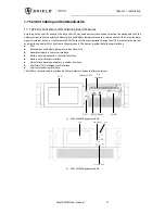
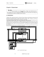
For single UPS rack module installation the EPO button on the front panel of the UPS rack controls the emergency stop
of UPS modules and bypass static switch and also supports remote emergency power off function that can be used to
shut down the UPS rack module remotely.
Note
1. The remote EPO switch must provide normally open or normally closed dry contactor signals.
2. The open circuit voltage is 24Vdc, and the current is less than 20mA.
3. Normally closed EPO-J4 terminals: Pin 1 and pin 2 have been connected in factory and located on the dry contactor
board.
4. Set EPO function as available with monitoring software on PC before using remote EPO function.
UPS1
Dry contact board
J4-3
J4-4
(a)
Single unit
UPS1
Dry contact board
J4-3
J4-4
UPS2
Dry contact board
J4-3
J4-4
(b)
Parallel system
Fig.3- 1: Circuit diagram of EPO
警告
危 险
Summary of Contents for M10U
Page 1: ......
Page 9: ......
Page 71: ...Appendix B Power Connection of Modular System 62 Shield M10U user manual ...

