shelolab SM10HP-2 Installation And Operation Manual Download Page 40


40 | 

P a g e


UNIT SPECIFICATIONS 

These ovens are 220 - 240 voltage units. Please refer to the oven

’s data plate for individual 

electrical specifications. 

Technical data specified applies to units with standard equipment at an ambient temperature of 
25°C and a voltage fluctuation of ±10%. The temperatures specified are determined in accordance 
to factory standard following DIN 12880 respecting the recommended wall clearances of 10% of the 
height, width, and depth of the inner chamber. All indications are average values, typical for units 
produced in the series. We reserve the right to alter technical specifications at all times. 
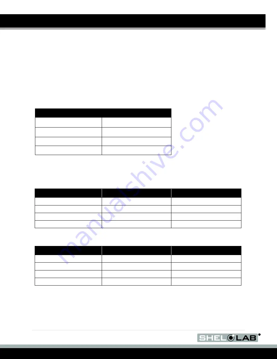
 

W

EIGHT


Model 

Shipping 

SMO10HP-2  

660 lbs. / 299.4kgs 

SMO14HP-2  

555 lbs. / 251.7kgs 

SMO34HP-2  

675 lbs. / 306.2kgs 

SMO38HP-2  

1025 lbs. / 465.0kgs 


D

IMENSIONS


By Inches 

Model 

Exterior W × D × H 

Interior W × D × H 

SMO10HP-2  

44 x 28.25 x 55.1 in 

30 x 19.75 x 30.1 in 

SMO14HP-2  

59 x 29 x 57 in 

44 x 20.5 x 36 in 

SMO34HP-2  

43 x 34.25 x 85.5 in 

31.5 x 26 x 60.5 in 

SMO38HP-2  

68.5 x 33 x 78.5 in 

48 x 25.5 x 54 in 


By centimeters 

Model 

Exterior W × D × H 

Interior W × D × H 

SMO10HP-2  

112 x 72 x 142 cm 

65.5 x 68 x 62 cm 

SMO14HP-2 

149.8 x 73.6 x 144.8 cm 

76 x 50 x 77 cm 

SMO34HP-2 

109 x 87  x 217 cm 

80 x 66 x 153.6 cm 

SMO38HP-2 

174 x 83x 199 cm 

121 x 64.7 x 137 cm 


Summary of Contents for SM10HP-2

Page 1: ...Installation and Operation Manual SMO34HP 2 SMO38HP 2 SMO14HP 2 SM10HP 2 Previously Designated HF25 2 HF37 2 HF15 2 HF10 2 SMO HIGH PERFORMANCE OVENS 220 240 Voltage ...

Page 2: ...HP 2 These units are TÜV CUE listed as forced air ovens for professional industrial or educational use where the preparation or testing of materials is done at an ambient air pressure range of 22 14 31 3 inHg 75 106 kPa and no flammable volatile or combustible materials are being heated The units have been tested to the following requirements CAN CSA C22 2 No 61010 1 2012 CAN CSA C22 2 No 61010 2 ...

Page 3: ... Installation 15 GRAPHIC SYMBOLS 16 CONTROL PANEL OVERVIEW 18 OPERATION 21 Operating Precautions 21 Preparing the Oven for Use 24 Prepare for First Use Burn In 24 Set the Temperature Set Point 25 First Use Burn In 26 Temperature Accuracy Verification 28 Set the Over Temperature Limit 30 OTL Activation During Normal Operations 31 Programming a Heating Profile 31 Positive Venting of Exhaust 32 USER ...

Page 4: ...sure that all operators are given appropriate training before the oven begins service Your oven and its recommended accessories have been designed and tested to meet strict safety requirements For continued safe operation of your oven always follow basic safety precautions including Follow any local or regional ordinances in your area regarding the use of this unit Only use the oven for its intend...

Page 5: ...ACTING ASSISTANCE If you are unable to resolve a technical issue with the oven please contact Sheldon Technical Support Phone hours for Sheldon Technical Support are 6am 4 30pm Pacific Coast Time west coast of the United States UTC 8 Please have the following information ready when calling or emailing Technical Support the model number and the serial number These will be found on the unit s data p...

Page 6: ...lly check all packaging before discarding Save the shipping carton until you are certain that the unit and its accessories function properly INSPECTING THE SHIPMENT Carefully inspect the shipping carton for damage Report any damage to the carrier service that delivered the SMOHP oven If the carton is not damaged open the carton and remove the contents The unit should come with an Installation and ...

Page 7: ...nt Connect Wire Braid 6 gauge 6 inches 15 cm Exhaust Vent Intake Vent Power Panel Back Control Panel Temperature Sensor Probes Chamber Gasket Power Exhaust Outlet 6 20R Fuse Holders for External Receptacle 2 amps each Chamber Ceiling Liner Power Supply Feed Shelf Standard Mounting Rail ...

Page 8: ...mperature Sensor Probes Chamber Ceiling Liner Permanent Connect Wire Braid 6 gauge 6 inches 15 cm Control Panel Exhaust Vent Intake Vent Chamber Liner Gasket Shelf Standard Mounting Rail Fuse Holders for External Receptacle 2 amps each Power Exhaust Outlet 6 20R Power Supply Feed ...

Page 9: ...st Vent Control Panel Chamber Gasket Temperature Sensor Probes Chamber Ceiling Liner Power Panel Back Permanent Connect Wire Braid 10 gauge 6 inches 15 cm Fuse Holders for External Receptacle 2 amps each Power Exhaust Outlet 6 20R Power Supply Feed Shelf Standard Mounting Rail ...

Page 10: ...l Back Fuse Holders for External Receptacle 2 amps each Power Exhaust Outlet 6 20R Intake Vent Exhaust Vent Control Panel Chamber Ceiling Liner Door Gasket Permanent Connect Wire Braid 10 gauge 6 inches 15 cm Power Supply Feed Temperature Sensor Probes In Chamber Figure 4 SMO10HP 2 ...

Page 11: ...ions of the oven temperature display The reference device must be accurate to at least 0 1 C and should be regularly calibrated preferably by a third party For best results use a digital device with a thermocouple or other remote reading probe Remote readings avoid oven chamber door openings during verification and calibration procedures This avoids subsequent waits for the chamber temperature to ...

Page 12: ...ther channeling 12 inches 30cm of vertical clearance will suffice Make sure the intake and exhaust vent remain unobstructed Do not place objects on top of oven aside from the power exhaust accessory described in the manual Operating the unit outside of these conditions may adversely affect the oven temperature range and stability For conditions outside of those listed above please contact your dis...

Page 13: ...t vary more than 10 from the data plate rating Damage to the oven may result if supplied voltage varies more than 10 Use a separate circuit to prevent loss of the unit due to overloading or circuit failure A switch or circuit breaker must be used in the building installation to protect against overcurrent conditions o The required circuit breakers are SMO10HP 2 30 amps SMO14HP 2 30 amps SMO34HP 2 ...

Page 14: ...ate lifting devices that are sufficiently rated for these loads Follow these guidelines when lifting the oven Lift the oven only from its bottom surface Doors handles and knobs are not adequate for lifting or stabilization Restrain the oven completely while lifting or transporting so it cannot tip Remove all moving parts such as shelves and trays and lock doors in the closed position during transf...

Page 15: ...d installation SHELVING INSTALLATION The horizontal airflow within the chamber moves from the small duct holes on the right hand side of the chamber to the large holes on the left side Place the shelves so they do not obstruct the duct holes on either side in order to maximize airflow across the shelf space Perform the following steps to install the SMO HP shelves 1 Install the shelf clips in the ...

Page 16: ...able Temperature Indique température réglable Indicates AC Power Repère le courant alternative Indicates I ON and O OFF I repère de la position MARCHE de l interrupteur d alimentation O repère de la position ARRÊT de l interrupteur d alimentation Indicates protective earth ground Repère terre électrique Indicates UP and DOWN respectively Touches de déplacements respectifs vers le HAUT et le BA Ind...

Page 17: ...17 P a g e GRAPHIC SYMBOLS CONTINUED This page left blank ...

Page 18: ...ven An orange ramp symbol illuminates when the controller is running a heating profile Controller Modes As shipped from the factory the controller boots up in its heating profile function mode ready to be programed and then launch a profile While on the home page in heating profile mode the up arrow button launches the heating profile if one has been programed This button also aborts a heating pro...

Page 19: ... between parameters and unlocks most parameters for adjustment Parameters blink continually when unlocked Pressing the Program button while a parameter is blinking will save the currently shown value as the new parameter value and advance to the next parameter The Exit button returns the display to the previous page and can also be used to take a parameter out of its flashing adjustable mode Doing...

Page 20: ...20 P a g e OPERATION CONTINUED This page left blank ...

Page 21: ...ybe hazardous to or noxious for operating personal If either is the case oven exhaust should be positively ventilated to a location outside workspace in accordance with national and local regulations 7 Do not place sealed or filled containers in the oven These may burst open when the chamber is under vacuum 8 Do not place alcohol or mercury thermometers in the oven 9 The oven is not designed for u...

Page 22: ...od and an option controller value The option controller value activates or deactivates an external exhaust blower fan plugged into the external power outlet and mounted on the oven exhaust vent The external exhaust blower must be purchased separately Please see the Operation and Programing JUMO dTRON Guide for how to program a heating profile The heating rates given for the oven are for a 25 C env...

Page 23: ...er venting A power exhaust increases the rate of air exchange within the oven chamber and impacts temperature performance and cooling rates by removing heated chamber air The Over Temperature Limit System The OTL is a backup mechanical heating control system that operates independently of the oven digital controller It consists of a mechanical thermostat control wired by a fluid capillary to an in...

Page 24: ... Operation section Prepare for First Use Burn In page 24 Set the Temperature Set Point for the burn in page 25 First Use Burn In page 26 Optional Temperature Verification page 28 Set the Over Temperature Limit for you application temperature page 30 PREPARE FOR FIRST USE BURN IN If the oven is being run for the first time out of the box perform the steps below followed by the Burn In procedure to ...

Page 25: ...he oven will ramp up to this temperature and run at it indefinitely o Please see pages 16 17 of the Operation and Programming Guide JUMO dTRON for how to place the unit in single set point mode Unlock and adjust the temperature set point This is the simplest option when performing the First Use Burn In and leaves the oven controller in its heating profile function mode See below Unlock and Adjust ...

Page 26: ...ing 200 C allow the oven run for a minimum of 1 hour at temperature a If still producing smoke after 1 hour run at 200 C until smoke from the heating elements dissipates After the Burn In is complete you may set the oven to run at your application constant temperature set point or program a heating profile You may also perform an optional accuracy verification of the temperature display Always set...

Page 27: ...27 P a g e OPERATION CONTINUED This page left blank ...

Page 28: ...through the chamber door space Use heat resistant non marking tape to secure the wires and probe heads and seal any gaps in the door space The door must close and latch fully Place the sensor probe of the temperature reference device as close as possible to the geometric center of the oven chamber A thermocouple sensor probe sleeve may be taped to the shelving as long as the exposed copper end is ...

Page 29: ... within the acceptable range of your protocol the display is accurately showing the oven chamber air temperature The Temperature Verification procedure is now complete b See step 2 if a difference falls outside the acceptable range of your protocol Reference Device 2 Perform a temperature calibration to match the controller display to the actual chamber temperature if a difference falls outside yo...

Page 30: ...plication temperature or a set point equal to the highest temperature of your application heating profile 3 Wait 30 minutes after the oven has achieved the set point for the chamber to stabilize before setting the OTL 4 Turn the Over Temperature Limit control dial counterclockwise until the red Over Temperature Limit Activated light illuminates 5 Slowly turn the dial clockwise until the Over Tempe...

Page 31: ...roller and display unit or its sensor probe has failed and must be replaced in order to maintain safe operation of the oven If the OTL activated during normal operations adjust it very slightly clockwise to increase the setting If the OTL continues to interrupt heating of the oven chamber and there no obvious external sources of nearby heating autoclaves another oven depower the oven and allow the...

Page 32: ...ven but leave the assembly in place 2 Mount the exhaust blower on the exhaust vent cover assembly aligning the blower and the assembly s screw holes a The open side of the blower s mounting body should go over the sliding handle of the exhaust port s vent cover 3 Reinstall the screws to secure the exhaust vent assembly and exhaust blower to the oven 4 Plug the power exhaust into the 230 volt outle...

Page 33: ...33 P a g e OPERATION CONTINUED This page left blank ...

Page 34: ... or abrasives these will damage the chamber liner Consult with the manufacturer or their agent if you have any doubts about the compatibility of decontamination or cleaning agents with the parts of the equipment or with material contained in it Warning Never clean the unit with alcohol or flammable cleaners Avertissement Ne jamais nettoyer l appareil à l alcool ou avec des nettoyants inflammables ...

Page 35: ...al or plastic Contact your local Site Safety Officer for detailed information on the disinfectants compatible with your application or process 3 If permitted by your protocol remove all interior accessories shelving and other non attached items from the chamber when disinfecting 4 Disinfect all surfaces in the chamber making sure thoroughly disinfect the corners Exercise care to avoid damaging the...

Page 36: ...e wires and probe heads and seal any gaps The door must close and latch fully Secure the wiring and cover any gaps in the door space using heat resistant non stick tape Place the sensor probe of the temperature reference device as close as possible to the geometric center of the oven chamber A thermocouple sensor probe sleeve may be taped to the shelving as long as the exposed copper end is 2 inch...

Page 37: ...ion procedure is now complete b See step 2 if a difference falls outside the acceptable range of your protocol Reference Device Home Page 2 The display requires calibration a The difference also known as an error between the reference device and the display is an offset Examples of offset values Reference Sensor Reading Oven Temp Display Offset Value 152 0 C 150 C 2 147 0 C 150 C 3 b Note the offs...

Page 38: ...b The Input 1 option will be the first to appear in the Input menu The Input Menu 7 Enter the Input 1 Menu a Press the Program button to enter the Input 1 menu b Sens will be the first option to appear in this menu Sens Option 8 Use the arrow keys to scroll to the OFFS Offset parameter a Scroll to the Offset calibration parameter to enter the offset Offset Parameter 9 Enter the temperature offset ...

Page 39: ... the readings are the same or the difference between the two falls within the acceptable range of your protocol the oven is calibrated for temperature The Temperature Calibration procedure is complete b See next step if the difference between the readings stills falls outside your protocol acceptable range Reference Device Set Temperature 13 If the two readings still fall outside your protocol acc...

Page 40: ...r units produced in the series We reserve the right to alter technical specifications at all times WEIGHT Model Shipping SMO10HP 2 660 lbs 299 4kgs SMO14HP 2 555 lbs 251 7kgs SMO34HP 2 675 lbs 306 2kgs SMO38HP 2 1025 lbs 465 0kgs DIMENSIONS By Inches Model Exterior W D H Interior W D H SMO10HP 2 44 x 28 25 x 55 1 in 30 x 19 75 x 30 1 in SMO14HP 2 59 x 29 x 57 in 44 x 20 5 x 36 in SMO34HP 2 43 x 34...

Page 41: ...g SMO34HP 2 75 lbs 34 kg 440 lbs 204 kg SMO38HP 1 75 lbs 34 kg 900 lbs 408 kg TEMPERATURE Model Range Uniformity Stability SMO10HP 2 Amb 10 to 260 C 2 3 C 150 C 0 2 C SMO14HP 2 Amb 10 to 260 C 2 3 C 150 C 0 2 C SMO34HP 2 Amb 10 to 260 C 2 0 C 100 C 0 2 C SMO38HP 2 Amb 10 to 260 C 2 5 C 150 C 0 2 C POWER Model AC Voltage Amperage Frequency Phase SMO10HP 2 220 240 26 50 60 Hz 1 SMO14HP 2 220 240 26 ...

Page 42: ...lf Assembly 19 x 29 SMO10HP 2 995 00007 Shelf Assembly 23 x 31 SMO34HP 2 995 00005 Shelf 21 x 23 SMO38HP 2 5120941 If you have the Part Number for an item you may order it directly from Sheldon Manufacturing by calling 1 800 322 4897 extension 3 If you are uncertain that you have the correct Part Number or if you need that specific item please contact Sheldon Technical Support for help at 1 800 32...

Page 43: ...43 P a g e REPLACEMENT PART LIST This page left blank ...

Page 44: ......

Reviews: