1 – 5
UX-A1000U
4
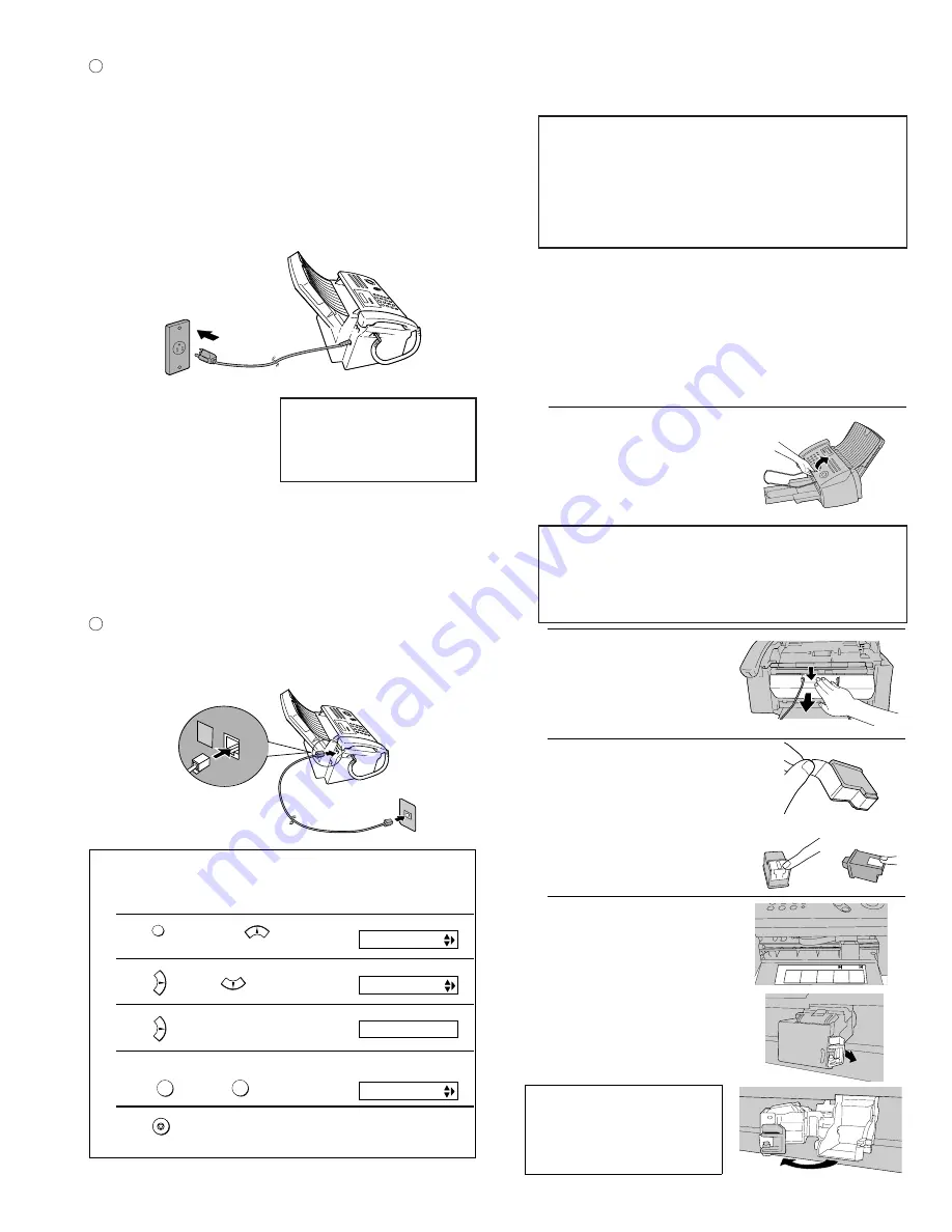
Insert one end of the line cord into the jack on the back of the ma-
chine marked TEL. LINE. Insert the other end into a standard (RJ11C)
single-line wall telephone jack.
Setting the dial mode
The fax machine is set for tone dialing. If you are on a pulse dial line, you must
set the fax machine for pulse dialing. Press the panel keys as follows:
1
Press
once and
3 times.
2
Press
once and
4 times.
3
Press
once.
4
Select the dial mode:
TONE:
PULSE:
5
Press
to exit.
FUNCTION
1
2
STOP
Display:
The display briefly shows
your selection, then:
OPTION SETTING
DIAL MODE
DISTINCTIVE
1=TONE, 2=PULSE
TEL.LINE
L.SET
3
Plug the power cord into a 120 V, 60 Hz, grounded AC (3-prong)
outlet.
Caution!
•
Do not plug the power cord into any other kind of outlet. This will
damage the machine and is not covered under the warranty.
•
Make sure you have removed all of the packing tape before
plugging in the power cord. Plugging in the power cord
without doing so may damage the machine.
•
The machine does not have a power on/off switch, so the power
is turned on and off by simply plugging in or unplugging the power
cord.
Note: If your area experiences a high incidence of lightning or
power surges, we recommend that you install surge protectors for
the power and telephonelines. Surge protectors can be purchased
at most telephone specialty stores.
“CHECK CARTRIDGE” normally
appears in the display the first
time you plug in the machine.
This message appears until you
install the print cartridge.
1
Open the operation panel.
3. Installing the Print Cartridge
•
When replacing the print cartridge, be sure to use a SHARP UX-C70B
cartridge.
2
Open the print compartment cover.
•
Press as shown and pull the cover
toward you.
3
Remove only the tape from the the new
cartridge.
•
Important: Make sure you remove all
of the tape.
•
CAUTION! DO NOT touch the gold
contact area of the cartridge.
4
Make sure the cartridge holder is
between the "CARTRIDGE EXCHANGE
AREA" arrows on the label, and then
pull the green lever and open the
cartridge holder cover.
•
If you are replacing the cartridge,
remove the old cartridge. If you are
going to use the old cartridge again,
place it in an air-tight container.
•
CAUTION! DO NOT touch the contact
area inside the carriage carrier.
Note: If the print compartment cover is left
open for approximately 30 minutes with a
cartridge installed, the cartridge will
automatically return to its home position. To
make the cartridge return to the CARTRIDGE
EXCHANGE AREA when this has happened,
close the cover and then open it again.
NO GOOD
NO GOOD
Caution!
Do not open the print compartment cover of the machine while it is
printing. If opened while printing, printing will stop.
Note: Keep ink cartridges sealed in their packages until you are ready
to install them. It is recommended that you do not use a cartridge that
has been left unused for a long time after opening, as the print quality
may be considerably degraded.
•
Make sure the power cord of the machine is plugged in and paper is
loaded
before installing or replacing the print cartridge.
If PRINTER ERROR or PRINTER ERROR/CHECK PAPER
appears...
In the event that the display shows either of the above mes-
sages, you must clear the error before installing the print
cartridge. The error can usually be cleared by opening and
closing the print compartment cover (see Step 2), or if a paper
jam has occurred, by removing the paper jam.
Print cartridge yield (at 4% coverage)
Initial cartridge
Ink save mode ON:Approx. 300 letter pages
Ink save mode OFF:Approx. 200 letter pages
Replacement cartridge (SHARP UX-C70B)
Ink save mode ON:Approx. 600 letter pages
Ink save mode OFF:Approx. 400 letter pages
Ink Save mode is initially turned off.
Summary of Contents for UX-A1000
Page 51: ...UX A1000U 3 13 M E M O ...
Page 81: ...UX A1000U Control PWB parts layout Top side 6 8 DRSNS BROWN ORGSNS ORANGE FRSNS RED ...
Page 82: ...UX A1000U Control PWB parts layout Bottom side 6 9 FU101 FU100 ...
Page 86: ...UX A1000U TEL LIU PWB parts layout Top side 6 13 TEL LIU PWB parts layout Bottom side ...
Page 91: ...UX A1000U P IN YELLOW FU1 GREEN 3 3V Printer PWB parts layout Top side 6 18 ...
Page 92: ...UX A1000U Printer PWB parts layout Bottom side 6 19 ...
Page 98: ...UX A1000U FPC FPC Ink PWB parts layout Top side Ink PWB parts layout Bottom side 6 25 ...


