TM150
OTHERS
6 – 12
CONFIDENTIAL
DRAFT
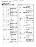
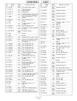
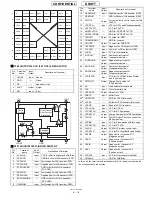
51
VSYNC
Input/
Output
Vertical synchronization signal
52
HSYNC
Input/
Output
Horizontal synchronization signal
53
EXCS_B3
Input/
Output
Chip select output 3
(internal decode output) (Not used)
54
XIN
Input
Oscillation circuit input/External
clock input signal Clock input for full
scan
55
SUBDB6
Input/
Output
Data bus for External display
56
RESET_B
Input
Master reset (All registers are
initialized when Low is activated)
57
SUBDB0
Input/
Output
Data bus for External display
58
SUBDB2
Input/
Output
Data bus for External display
59
HSD5
Input/
Output
Data bus for high-speed serial transfer
60
DB0
Input/
Output
Data bus
61
HSD4
Input/
Output
Data bus for high-speed serial transfer
62
EXCS_B2
Input/
Output
Chip select output 2 (internal
decode output) (Not used)
63
GDATA[5] (G5)
Output Display panel G output signal
64
GDATA[4] (G4)
Output Display panel G output signal
65
GDATA[3] (G3)
Output Display panel G output signal
66
SUBDB3
Input/
Output
Data bus for External display
67
SUBDB4
Input/
Output
Data bus for External display
68
HSD7
Input/
Output
Data bus for high-speed serial transfer
69
DB1
Input/
Output
Data bus
70
DB2
Input/
Output
Data bus
71
DB3
Input/
Output
Data bus
72
DB4
Input/
Output
Data bus
73
STKCHK
Input
Setting BS-related output terminal to
Hi-z when a stack is installed (Con-
nected to GND normally)
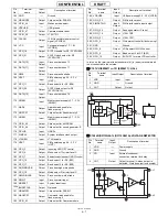
74
VDDCORE
-
CORE Power supply 1.8 V (1.6 V~ 2.0 V)
75
GND
-
Logic ground
76
VDDIO
-
IO Power supply 3.0 V (2.7 V~ 3.3 V)
77
GDATA[2] (G2)
Output Display panel G output signal
78
SUBDB5
Input/
Output
Data bus for External display
79
BSCLK
Input/
Output
External Bit Stream data clock
80
SUBCK
Output Clock for External display
81
DB5
Input/
Output
Data bus
82
VDDIO
-
IO Power supply 3.0 V (2.7 V~ 3.3 V)
83
GND
-
Logic ground
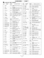
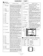
Pin
No.
Terminal
name
Input/
Output
Description of terminal
84
VDDCORE
-
CORE Power supply 1.8 V (1.6 V~ 2.0 V)
85
CAMCK
Output Clock for camera operation
86
GDATA[1] (G1)
Output Display panel G output signal
87
GDATA[0] (G0)
Output Display panel G output signal
88
RDATA[5] (R5)
Output Display panel R output signal
89
RDATA[4] (R4)
Output Display panel R output signal
90
VDDCORE
-
CORE Power supply 1.8 V (1.6 V~ 2.0 V)
91
P W M L C D /
PORT4
Output PWM LCD output General-purpose
PORT output (default) (Not used)
92
BSBLK_B
Input/
Output
External Bit Stream data effective
signal ("High" is active when
transferring the data)
93
DB6
Input/
Output
Data bus
94
DB7
Input/
Output
Data bus
95
DB8
Input/
Output
Data bus
96
DB9
Input/
Output
Data bus
97
VDDIO
-
IO Power supply 3.0 V (2.7 V~ 3.3 V)
98
RDATA[3] (R3)
Output Display panel R output signal
99
RDATA[2] (R2)
Output Display panel R output signal
100
RDATA[1] (R1)
Output Display panel R output signal
101
RDATA[0] (R0)
Output Display panel R output signal
102
MP4_P0
Output MPEG4 control
103
EXCS_B0
Input/
Output
Chip select output 0 (internal
decode output) (Not used)
104
BSPIXEL7
Input/
Output
External Bit Stream data bus
105
BSVS_B
Input/
Output
External Bit Stream vertical synchro-
nization signal ("Low" is active)
106
DB10
Input/
Output
Data bus
107
DB11
Input/
Output
Data bus
108
DB12
Input/
Output
Data bus
109
MP4_PLLCK
Output MPEG4ASIC clock 15.36 MHz/CPU
supply XIN clock (Not used)
110
SUBDB7
Input/
Output
Data bus for External display
111
GND
-
Logic ground
112
DA0
Input/
Output
Address input for chip select
decode
113
BSPIXEL0
Input/
Output
External Bit Stream data bus
114
DCS_B
Input
Chip select input dedicated for chip
select decode
115
VDDIO
-
IO Power supply 3.0 V (2.7 V~ 3.3 V)
116
BSPIXEL6
Input/
Output
External Bit Stream data bus
117
SE_DO/PORT0
Output Data output for 4-wire serial IF (default)
General-purpose PORT output
118
DB13
Input/
Output
Data bus
Pin
No.
Terminal
name
Input/
Output
Description of terminal
*
*
*
*
*
*
Summary of Contents for TM150
Page 61: ...TM150 CIRCUIT DIAGRAM AND PWB LAYOUT 5 13 CONFIDENTIAL DRAFT MAIN PWB_FRONT ...
Page 62: ...TM150 CIRCUIT DIAGRAM AND PWB LAYOUT 5 14 CONFIDENTIAL DRAFT MAIN PWB_REAR ...
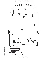
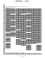
Page 63: ...TM150 CIRCUIT DIAGRAM AND PWB LAYOUT 5 15 CONFIDENTIAL DRAFT LCD PWB_FRONT ...
Page 64: ...TM150 CIRCUIT DIAGRAM AND PWB LAYOUT 5 16 CONFIDENTIAL DRAFT LCD PWB_REAR ...

