TM150
ADJUSTMENTS, PERFORMANCE CHECK, AND FIRMWARE UPGRADE
2 – 12
CONFIDENTIAL
DRAFT
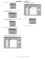
4-5-2. Default setting for the program.
• Activate the program and set defaults.
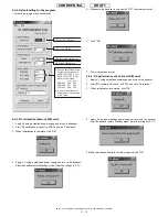
4-5-3. RF calibration (Remove SIM card)
1.
Apply 4 V using a stabilized power supply and turn on the handset.
2.
Start "RF calibration & check" on SPST and click "Calibration".
3.
When initialization is complete, click "OK".
4.
Apply 4 V using a stabilized power supply and turn on the handset.
After the handset enters Standby mode, lower the voltage to 3.7 V.
5. Make sure the handset is on and click "OK". (Adjustment starts.)
6. Click "OK".
7. The initial screen returns.
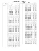
4-5-4. RF performance check (Insert SIM card)
1. Apply 4 V using a stabilized power supply and turn on the handset.
2. Start "RF calibration & check" on SPST and click "Calibration".
3. When initialization is complete, click "OK".
4. Apply 4 V using a stabilized power supply and turn on the handset.
After the handset enters Standby mode, lower the voltage to 3.7 V.
5.Make sure the handset is in the idle mode and click "OK"..
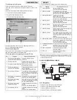
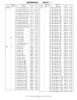
2) Set the GPIB No.
the COMport.
1) Select
3)Select the test instrument.
4) Set the GPIBaddress.
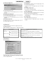
5) Set the"Cable Offset" values.
For cables with connector
UKOG-1031YCZZ (1.0m)
UKOG-1032YCZZ (0.5m)
the values as follows:
GSM9 00
0.48 0.27
DCS1800
0.67 0.38
PCS1900
0.68 0.38
*
:
:
:
TM150
(1.0m) (0.5m)
In case of an attenuator
addition state, 6 db addition
to the value.
Summary of Contents for TM150
Page 61: ...TM150 CIRCUIT DIAGRAM AND PWB LAYOUT 5 13 CONFIDENTIAL DRAFT MAIN PWB_FRONT ...
Page 62: ...TM150 CIRCUIT DIAGRAM AND PWB LAYOUT 5 14 CONFIDENTIAL DRAFT MAIN PWB_REAR ...
Page 63: ...TM150 CIRCUIT DIAGRAM AND PWB LAYOUT 5 15 CONFIDENTIAL DRAFT LCD PWB_FRONT ...
Page 64: ...TM150 CIRCUIT DIAGRAM AND PWB LAYOUT 5 16 CONFIDENTIAL DRAFT LCD PWB_REAR ...


