TM150
OTHERS
6 – 9
CONFIDENTIAL
DRAFT
■
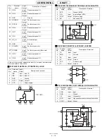
IC502 VHIBU7870KN-1L (BU7870KN): USB CONTROLLER
In this unit, the terminal withasterisk mark (
*
) is (open) terminal which
is not connected to the outside.
■
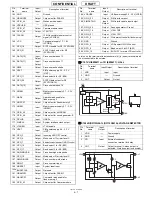
IC505 VHIXC620930-1L (XC620930): REGULATOR
In this unit, the terminal withasterisk mark (
*
) is (open) terminal which
is not connected to the outside.
■
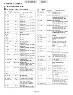
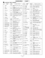
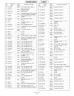
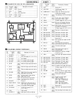
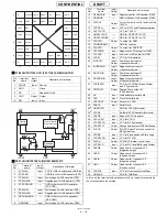
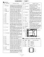
IC506 RUNTZA005AFZZL (UGNZ2): BLUETOOTH MODULE
Pin
No.
Terminal
name
Input/
Output
Description of terminal
1
MODESEL1
Input
Operation mode switching 1
2
MODESEL2
Input
Operation mode switching 2
3
UART_RXD
Output
UART_RXD output
4
UART_TXD
Input
UART_TXD input
5
CPUVDD
-
Digital power supply
6
UART_RTS
Input
UART_RTS input
7
BSYNC
Input
BSYNC input
8
UART_CTS
Output
UART_CTS output
9
BDATA
Input
BDATA input
10
BCNT
Input
BDATA input control
11
MODESEL3
Input
Operation mode switching 3
12
TXANAOUT
Output
Hands free sending external output
13
RXANAIN
Input
Hands free receiving external input
14
GND1
-
Ground
15
RXANAOUT
Output
Hands free receiving output
16
TXANAIN
Input
Hands free sending input
17
NC
-
Not used
18
BDATA/CTS
Input/
Output
BDATA/CTS switching external
input/output
19
BSYNC/RTS
Output
BSYNC/RTS switching external output
20
USBD-/TXD
Input/
Output
USBD-/TXD switching external
input/output
21
GND2
-
Ground
22
USBD+/RXD
Input/
Output
USBD+/RXD switching external
input/output
23
CP
Input/
Output
CP input/output
24
CPU_USB_D-
Input/
Output
CPU_USB_D- input/output
25
REG33
-
Power supply voltage for USB
26
PU15
Output
PMOS open drain output
27
PUEA
Input
PU15 control input
28
GND3
-
Ground
20
21
14 GND1
GND2
MODESEL1
MODESEL2
U
A
R
T_RXD
U
A
R
T_TXD
U
A
R
T_R
TS
BSYNC
CPUVDD
USBD-/TXD
BSYNC/R
T
S
BD
A
T
A/CTS
NC
TXANAIN
RXANA
OUT
USBD+/RXD
CP
CPU_USB_D-
REG33
PU15
PUEA
GND3
RXANAIN
TXANAOUT
MODESEL3
BCNT
BDATA
UART_CTS
19
15
16
17
MODE 0,1,2: ON
MODE 3,5: OFF
CPUVDD
CPUVDD
CPUVDD
CPUVDD
DEC
H: ON
L: OFF
CPUVDD
CPUVDD
CPUVDD
CPUVDD
CPUVDD
CPUVDD
MODE 0,1,2: OFF
MODE 3,5: ON
MODE 0,2,3: OFF
MODE 1,5: ON
MODE 0,2,3,5: OFF
MODE 1: ON
MODE 0,2,3,5: L
MODE 1: H
MODE
0,2,3,5:
L
MODE
1:
H
MODE
0,2,3,5:
L
MODE
1:
H
MODE
0,1,3,5:
H
MODE
2:
L
MODE
0,1,5:
H
MODE
2,3:
L
MODE
0,1,5:
H
MODE
2,3:
L
MODE
0,1,5:
OFF
MODE
2,3:
ON
MODE
0,1,3,5:
H
MODE
2:
L
MODE
0,1,3,5:
OFF
MODE
2:
ON
10K
10K
MODE 0,1,2: ON
MODE 3,5: OFF
18
13
12
11
10
9
8
7
6
4
2
1
3
5
22
23
24
25
26
27
28
Pin
No.
Terminal
name
Input/
Output
Description of terminal
1
VIN
Input
Input
2
VSS
-
Ground
3
CE
Input
ON/OFF Control
4
NC
-
Not used
5
VOUT
Output
Output
Pin
No.
Terminal
name
Input/
Output
Description of terminal
1
USBP
Input/
Output
USB DATA+ (Not used)
2
USBN
Input/
Output
USB DATA- (Not used)
3
UART_RTS
Output UART/Ready to send to DTE
4
GND
-
Ground
5
GND
-
Ground
6
UART_TxD
Output UART/TxD to DTE
7
UART_RxD
Input
UART/RxD from DTE
8
UART_CTS
Input
UART/Clear to send from DTE
9
PIO8
Input/
Output
General purpose I/O
10
VCC_IO
Input
Positive supply voltage for IO voltage
Connect the VCC, if IO voltage is
same as VCC
11
VCC
Input
Main supply voltage input 1 Regulated
DC source recommended
12
PCM_OUT
Output PCM data stream output
13
PCM_SYNC
Input/
Output
Connection to PCM frame sync Input/
output of 8 kHz
14
XTAL_IN
Input
Ext clock in (Not used)
15
XTAL_OUT
Input
Ext clock out (Not used)
16
RESETB
Input
System reset
17
VDD18V
Output VDD_CORE decupling capacitor
18
PCMCLK
Input/
Output
Connction to PCM reference Clock
input/output of 256 kHz
19
PCM_IN
Input
PCM data stream input
20
PIO5
Input/
Output
General purpose I/O
+
-
1
2
3
CE
VSS
VIN
ON/OFF
Control
Current
Limit
Voltage
Reference
Each ciruit
5 VOUT
*
*
*
*
*
Summary of Contents for TM150
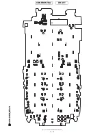
Page 61: ...TM150 CIRCUIT DIAGRAM AND PWB LAYOUT 5 13 CONFIDENTIAL DRAFT MAIN PWB_FRONT ...
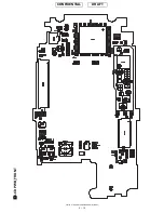
Page 62: ...TM150 CIRCUIT DIAGRAM AND PWB LAYOUT 5 14 CONFIDENTIAL DRAFT MAIN PWB_REAR ...
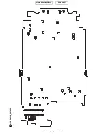
Page 63: ...TM150 CIRCUIT DIAGRAM AND PWB LAYOUT 5 15 CONFIDENTIAL DRAFT LCD PWB_FRONT ...
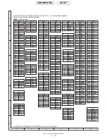
Page 64: ...TM150 CIRCUIT DIAGRAM AND PWB LAYOUT 5 16 CONFIDENTIAL DRAFT LCD PWB_REAR ...


