TM150
ADJUSTMENTS, PERFORMANCE CHECK, AND FIRMWARE UPGRADE
2 – 18
CONFIDENTIAL
DRAFT
4-6-2. Setup
1.
Set PWB and make connections as shown below.
Make sure connections are correct at the points shown below.
2. Apply 4 V using a stabilized power supply and turn on the handset.
3. Start RF test tool.
4. Select a COM port to which Data Cable is connected.
5. Press the "Initialize & Read Data" button.
6. The figre shown below appears (wait a few seconds).
7. Click "OK" to proceed.
4-6-3. Tests
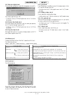
1) BAND Select & Channel
Select a band and a channel to test. Settings are applied to all tests.
[Procedure]
1. Select a band. (GSM900, DCS or PCS)
2. Select or enter a channel using Channel bar or Input box.
Hook
Hook
Hook
PWB
Hook
Hook
Hook
Red
PC
PWB repair jig
GSM Tester
(CMU 200)
Black
Data Cable
Points
Push
Band selection
Input box
Channel bar
Summary of Contents for TM150
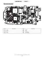
Page 61: ...TM150 CIRCUIT DIAGRAM AND PWB LAYOUT 5 13 CONFIDENTIAL DRAFT MAIN PWB_FRONT ...
Page 62: ...TM150 CIRCUIT DIAGRAM AND PWB LAYOUT 5 14 CONFIDENTIAL DRAFT MAIN PWB_REAR ...
Page 63: ...TM150 CIRCUIT DIAGRAM AND PWB LAYOUT 5 15 CONFIDENTIAL DRAFT LCD PWB_FRONT ...
Page 64: ...TM150 CIRCUIT DIAGRAM AND PWB LAYOUT 5 16 CONFIDENTIAL DRAFT LCD PWB_REAR ...

