9
LC-32LD145
LC-39LD145
Operation Manual (Continued)
English
- 8 -
Viewing the TV
TV Control button & Operation
1.
Up direction
2.
Down direction
3.
Programme/Volume / AV / Standby-On selection
switch
The Control button allows you to control the Volume/
Programme/ Source and Standby-On functions of
the TV.
To change volume:
Increase the volume by pushing
the button up. Decrease the volume by pushing the
button down.
To change channel:
Press the middle of the button,
the channel information banner will appear on screen.
Scroll through the stored channels by pushing the
button up or down
To change source:
Press the middle of the button
twice, the source list will appear on screen. Scroll
through the available sources by pushing the button
up or down.
To turn the TV off:
Press the middle of the button
down and hold it down for a few seconds, the TV will
turn into standby mode.
Inserting the Batteries into the Remote
Insert batteries in the remote before operating your TV.
Lift the cover on the back of the remote upward gently.
Install two
AAA
batteries. Make sure to match the +
and - ends of the batteries in the battery compartment
(observe the correct polarity) Replace the cover.
Connect Power
IMPORTANT
: The TV set is designed to operate on
220-240V AC, 50 Hz
socket. After unpacking, allow
the TV set to reach the ambient room temperature
before you connect the set to the mains. Plug the
power cable to the mains socket outlet.
Antenna/Cable Connection
Connect the “aerial” or “cable TV” plug to the AERIAL
INPUT (ANT) socket located on the back of the TV.
Notification
Manufactured under license from Dolby Laboratories.
TRADEMARK ACKNOWLEDGMENT
“Dolby” and the double-D symbol are
trademarks of Dolby Laboratories.
“HDMI, the HDMI logo and High-Definition Multimedia
Interface are trademarks or
registered trademarks of HDMI
Licensing LLC.”
Summary of Contents for LC-32LD145K
Page 12: ...12 LC 39LD145 LC 32LD145 English 21 Dimensional Drawings LC39LD145 ...
Page 15: ...15 LC 32LD145 LC 39LD145 3 Remove Speaker Wire 4 Remove AC Cord ...
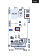
Page 17: ...17 LC 32LD145 LC 39LD145 4 1 1 General Block Diagram 0 1 ...
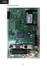
Page 18: ...18 LC 39LD145 LC 32LD145 5 1 2 MB82 Placement of Blocks 0 2 ...
Page 21: ...21 LC 32LD145 LC 39LD145 ...
Page 22: ...22 LC 39LD145 LC 32LD145 ...
Page 23: ...23 LC 32LD145 LC 39LD145 ...
Page 24: ...24 LC 39LD145 LC 32LD145 11 2 4 Pinning ...
Page 25: ...25 LC 32LD145 LC 39LD145 ...
Page 26: ...26 LC 39LD145 LC 32LD145 14 TS4962M optional 2 5W ...
Page 35: ...35 LC 32LD145 LC 39LD145 ...
Page 36: ...36 LC 39LD145 LC 32LD145 ...
Page 38: ...38 LC 39LD145 LC 32LD145 27 x16 Package Pinout Top view 96ball FBGA Package ...
Page 39: ...39 LC 32LD145 LC 39LD145 28 7 SCALER AND LVDS SOCKETS 7 1 LVDS sockets Block Diagram ...
Page 41: ...41 LC 32LD145 LC 39LD145 30 8 1 2 Features 8 1 3 Block Diagram ...
Page 42: ...42 LC 39LD145 LC 32LD145 31 8 1 4 Pinning ...
Page 44: ...44 LC 39LD145 LC 32LD145 33 8 2 3 Block Diagram 8 2 4 Pinning ...
Page 45: ...45 LC 32LD145 LC 39LD145 34 ...
Page 48: ...48 LC 39LD145 LC 32LD145 37 10 3 VGA CN711 10 4 SCART SC1 ...
Page 51: ...51 LC 32LD145 LC 39LD145 11 3 Options Options 1 RET BACK RET BACK Options 2 ...
Page 52: ...52 LC 39LD145 LC 32LD145 11 5 Source Settings 11 4 Tuning Settings RET BACK ...
Page 79: ...79 LC 32LD145 LC 39LD145 POWER BOARD 17IPS20 39 1 2 ...
Page 80: ...80 LC 32LD145 LC 39LD145 POWER BOARD 17IPS20 39 2 2 ...
Page 107: ...107 LC 32LD145 LC 39LD145 ...


