10
LC-39LD145
LC-32LD145
Operation Manual (Continued)
English
- 11 -
Connector
Type
Cables
Device
Scart
Connection
(back)
VGA
Connection
(back)
SIDE AV
PC/YPbPr
Audio
Connection
(side)
Side Audio
YPbPr or PC Connection Cable
(Not supplied)
HDMI
Connection
(back)
SPDIF
Connection
(back)
SIDE AV
Side AV
(Audio/Video)
Connection
(side)
HEADPHONE
Headphone
Connection
(side)
YPbPr Video
Connection
(back)
PC to YPbPr Connection Cable
USB
Connection
(side)
CI
Connection
(side)
CAM
module
Connections
NOTE
:
When connecting a device via the YPbPr or Side AV input, you must use a connection cable to
enable connection.
See the illustrations above.
|
You can use YPbPr to VGA cable (not supplied) to enable YPbPr
signal via VGA input.
|
You cannot use VGA and YPbPr at the same time.
|
To enable PC audio, you will need to
use the SIDE AV CONNECTION cable’s WHITE & RED inputs.
|
If an external device is connected via the SCART
socket, the TV will automatically switch to AV mode.
|
When receiving DTV channels (Mpeg4 H.264) or while in
Media Browser mode, output will not be available via the scart socket.
|
When using the wall mounting kit (available
from third party in the market), we recommend that you plug all your cables into the back of the TV before mounting
on the wall.
|
Insert or remove the CI module only when the TV is SWITCHED OFF. You should refer to the module
instruction manual for details of the settings.
Summary of Contents for LC-32LD145K
Page 12: ...12 LC 39LD145 LC 32LD145 English 21 Dimensional Drawings LC39LD145 ...
Page 15: ...15 LC 32LD145 LC 39LD145 3 Remove Speaker Wire 4 Remove AC Cord ...
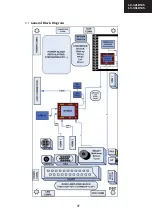
Page 17: ...17 LC 32LD145 LC 39LD145 4 1 1 General Block Diagram 0 1 ...
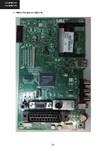
Page 18: ...18 LC 39LD145 LC 32LD145 5 1 2 MB82 Placement of Blocks 0 2 ...
Page 21: ...21 LC 32LD145 LC 39LD145 ...
Page 22: ...22 LC 39LD145 LC 32LD145 ...
Page 23: ...23 LC 32LD145 LC 39LD145 ...
Page 24: ...24 LC 39LD145 LC 32LD145 11 2 4 Pinning ...
Page 25: ...25 LC 32LD145 LC 39LD145 ...
Page 26: ...26 LC 39LD145 LC 32LD145 14 TS4962M optional 2 5W ...
Page 35: ...35 LC 32LD145 LC 39LD145 ...
Page 36: ...36 LC 39LD145 LC 32LD145 ...
Page 38: ...38 LC 39LD145 LC 32LD145 27 x16 Package Pinout Top view 96ball FBGA Package ...
Page 39: ...39 LC 32LD145 LC 39LD145 28 7 SCALER AND LVDS SOCKETS 7 1 LVDS sockets Block Diagram ...
Page 41: ...41 LC 32LD145 LC 39LD145 30 8 1 2 Features 8 1 3 Block Diagram ...
Page 42: ...42 LC 39LD145 LC 32LD145 31 8 1 4 Pinning ...
Page 44: ...44 LC 39LD145 LC 32LD145 33 8 2 3 Block Diagram 8 2 4 Pinning ...
Page 45: ...45 LC 32LD145 LC 39LD145 34 ...
Page 48: ...48 LC 39LD145 LC 32LD145 37 10 3 VGA CN711 10 4 SCART SC1 ...
Page 51: ...51 LC 32LD145 LC 39LD145 11 3 Options Options 1 RET BACK RET BACK Options 2 ...
Page 52: ...52 LC 39LD145 LC 32LD145 11 5 Source Settings 11 4 Tuning Settings RET BACK ...
Page 79: ...79 LC 32LD145 LC 39LD145 POWER BOARD 17IPS20 39 1 2 ...
Page 80: ...80 LC 32LD145 LC 39LD145 POWER BOARD 17IPS20 39 2 2 ...
Page 107: ...107 LC 32LD145 LC 39LD145 ...


