


FO-DC600U
(5) Speaker amplifier
The speaker amplifier monitors the line under the on-hook mode, out-
puts the buzzer sound generated by SUB ASIC, ringer sound, DTMF
generated from the modem, and line sound.
(4) Scanner control block
1) Image signal process block
The CIS is driven by MAIN ASIC (IC6), and the output video signal from
the CIS is input into IC6 through the amplifying circuit.
The ADC and buffer are provided in IC6, and the digital image process-
ing is performed.
2) Mechanical control block
The mechanical control block is mainly composed of MAIN ASIC to con-
trol the following.
(a) Scanner motor control
The revolution speed and timing of the scanner motor are controlled to
output the control signals to the motor driver (IC3).
(b) Verification stamp and LED lamp control
On/off of the end verification and LED lamp of CIS is controlled with
the software.
CIS
VIDEO
SIGNAL
AMPLIFIER
CIRCUIT
MAIN ASIC
(IC6)
CLOCK
Fig. 5
(6) Page memory block
W986416DH or MT48LC4M16A2TG (IC5): pin-54, TSOP
(64 Mb SDRAM)
The page memory block is composed of one SDRAM of 64 Mb, being
commonly used as the image memory. The memory is divided into the
page memory for the scanner and the page memory for printing.
This memory is controlled by the MAIN ASIC directly.
The page memory for scanner is composed of the partial area of IC5.
The image data of approx. one page (except in the super fine mode) of
the draft read with the scanner can be stored. They are stored until they
are contracted by CODEC function in MAIN ASIC.
The page memory for printing is composed of the remaining areas of
IC5 and can store approx. one page of the image data decoded by
CODEC function in MAIN ASIC. The data are stored until they are trans-
ferred to Printer PWB with the SUB ASIC and printed.
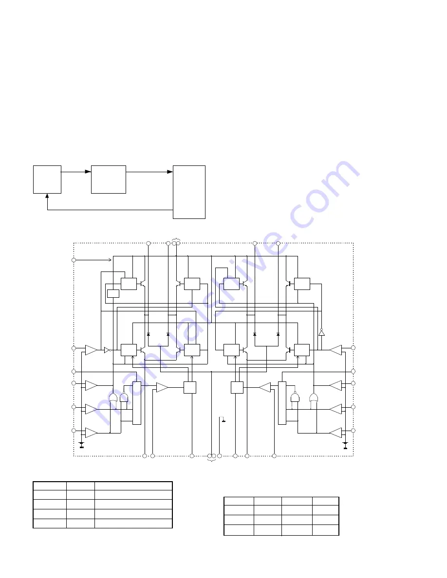
(7) Driver block
Sending motor driver (IC3: LB1845) ---- 28-pin DIP
This IC driver at the sending motor at the constant current with the bipo-
lar, chopper system.
–
+
–
+
–
+
–
+
–
+
–
+
–
+
–
+
–
+
–
+
PHASE2
VREF2
ENABLE2
I02
I12
CURRENT CONTROL
BLOCK
SENSE2
E2
ONE
SHOT
RC2
OUTPUT
BLOCK
PHASE1
VREF1
ENABLE1
I01
I11
CURRENT CONTROL
BLOCK
E1
SENSE1
ONE
SHOT
RC1
TSD
D-GN
D
GND
OUT2A
OUT2B
OUT1A
OUT1B
VCC 28
6
9
25
26
24
22
23
3
27
11 15
16
12
13
20
21
19
17
18
OUTPUT
BLOCK
OUTPUT
BLOCK
OUTPUT
BLOCK
OUTPUT
BLOCK
OUTPUT
BLOCK
OUTPUT
BLOCK
OUTPUT
BLOCK
4
VBB
14
8
1
7
2
Fig. 6
[Truth Table]
ENABLE
PHASE
OUTA
OUTB
L
H
H
L
L
L
L
H
H
–
OFF
OFF
Note: When ENABLE = H or I
0
= I
1
= H, the output is in OFF state.
I
0
I
1
Output Current
L
L
Vref/ (10 x R
E
) = I
OUT
H
L
Vref/ (15 x R
E
) = I
OUT
x 2/3
L
H
Vref/ (30 x R
E
) = I
OUT
x 1/3
H
H
0
5 – 14
Summary of Contents for FO-DC600
Page 98: ...FO DC600U Control PWB parts layout Top side 6 16 F1 F2 F5 ...
Page 99: ...FO DC600U Control PWB parts layout Bottom side 6 17 F100 F101 F102 ...
Page 101: ...FO DC600U LIU PWB parts layout Top side 6 19 ...
Page 102: ...FO DC600U LIU PWB parts layout Bottom side 6 20 ...
Page 105: ...FO DC600U Printer PWB parts layout Top side 6 23 ...
Page 106: ...FO DC600U Printer PWB parts layout Bottom side 6 24 ...