


FO-DC600U
2 – 9
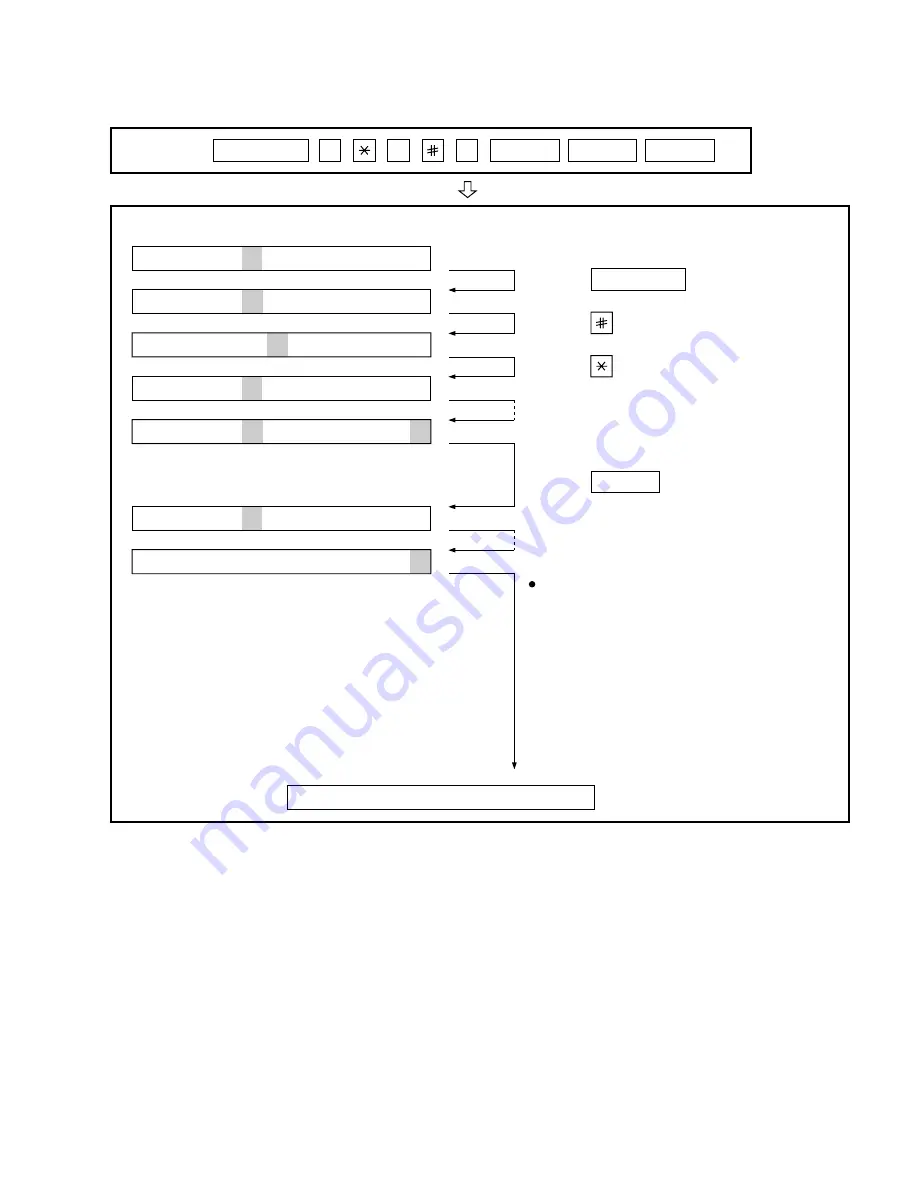
3. How to make soft switch setting
To enter the soft switch mode, make the following key entries in sequence.
Press
MENU
9
8
7
START
A
START
Press
MENU
key.
Press
key.
Press
key.
Bit1 - 8 are set.
Soft SW02 - 99 are set.
S W 01 = 1 0 0 0 0 0 0 0
S W 01 = 1 0 0 0 0 0 0 0
S W 01 = 1 0 0 0 0 0 0 0
S W 01 = 1 0 0 0 0 0 0 0
S W 02 = 0 0 0 0 0 0 0 0
S W 99 = 0 0 0 0 0 0 0 0
Press
key during setting.
To finish the settings halfway between
SW01 and SW99, press the STOP key.
In this case, the setting being done to
the SW No. on display will be nullified
while settings done to the preceding
SW No. remain in effect.
The soft switch mode is terminated.
S W 01 = 0 0 0 0 0 0 0 0
START
• SW1 to SW22 : For Line-1
• SW23 to SW44 : For Line-2
Summary of Contents for FO-DC600
Page 98: ...FO DC600U Control PWB parts layout Top side 6 16 F1 F2 F5 ...
Page 99: ...FO DC600U Control PWB parts layout Bottom side 6 17 F100 F101 F102 ...
Page 101: ...FO DC600U LIU PWB parts layout Top side 6 19 ...
Page 102: ...FO DC600U LIU PWB parts layout Bottom side 6 20 ...
Page 105: ...FO DC600U Printer PWB parts layout Top side 6 23 ...
Page 106: ...FO DC600U Printer PWB parts layout Bottom side 6 24 ...