1 – 8
FO-CC500A
FO-K01A
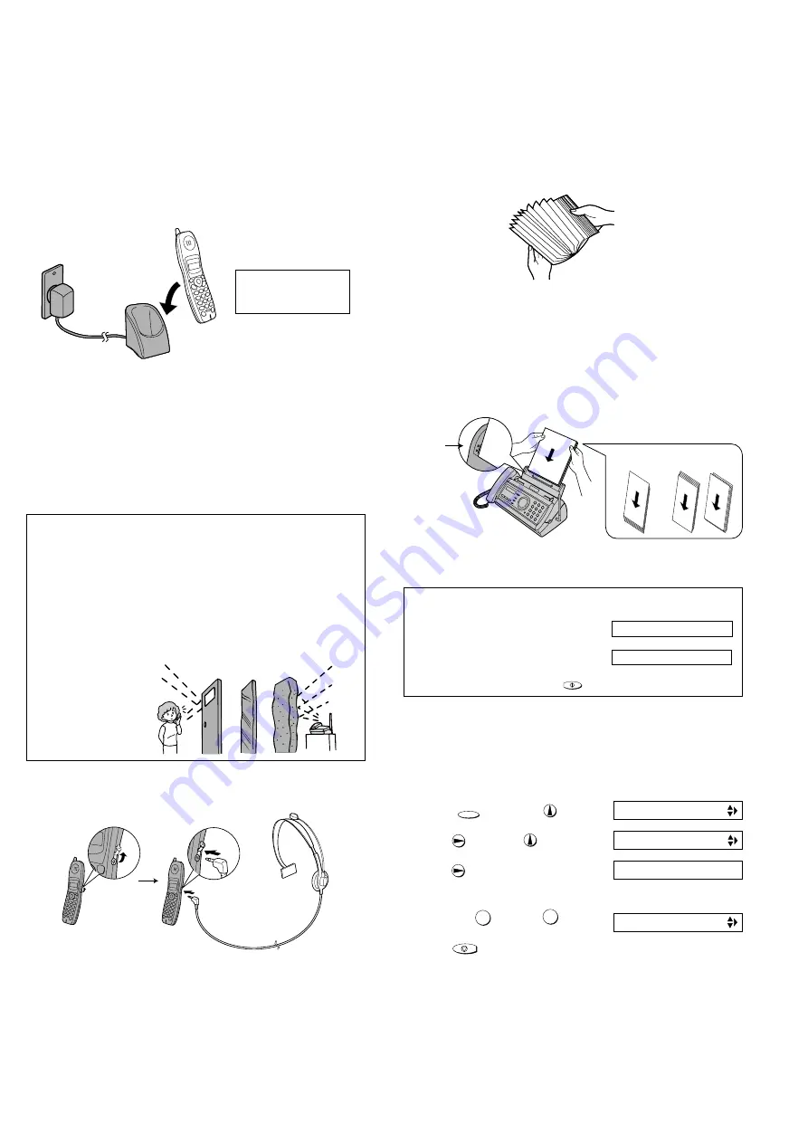
6. Loading printing paper
You can load up to 50 sheets of A4-size, 60 - 80 g/m
2
paper in the paper
tray (at room temperature; maximum stack height should not be higher
than the line on the tray).
1
Fan the paper, and then tap the edge against a flat surface to even
the stack. Make sure the stack edges are even.
2
Insert the stack of paper into the tray, PRINT SIDE DOWN.
•
If paper remains in the tray, take it out and combine it into a single
stack with the new paper.
•
Be sure to load the paper so that printing takes place on the print
side of the paper. Printing on the reverse side may result in poor
print quality.
•
GENTLY LOAD PAPER INTO THE PAPER TRAY.
•
DO NOT FORCE IT DOWN INTO THE FEED SLOT.
Correct
Incorrect
The stack
should not
be higher
than this line.
Note: Do not use paper that has already been printed on, or paper that
is curled.
Note: If at any time the display shows
the alternating messages at right, check
the printing paper. If the tray is empty,
add paper. If these is paper in the tray,
take it out and then reinsert it.
When you are finished, press .
START/MEMORY
ADD PAPER &
PRESS START KEY
↑
↑
4
Print contrast setting.
You fax has been set at the factory to print at normal contrast. If
desired, you can change the print contrast setting to LIGHT.
FUNCTION
1. Press once and once.
2. Press once and 3 times.
3. Press once.
4. Select the print contrast:
NORMAL: LIGHT:
5. Press to return to the date and time display.
1
2
STOP
OPTION SETTING
Display:
PRINT CONTRAST
1: NORMAL
COPY CUT-OFF
The display briefly shows
your selection, then:
4
Connecting a headset.
You can connect a headset (purchased separately) to the headset
socket. Remove the cap and insert the connector as shown.
Accessory cordless handsets (FO-K01)
♦
♦
♦
♦
♦
You can use up to 3 additional FO-K01 cordless handsets with the
fax machine.
♦
♦
♦
♦
♦
Please purchase accessory FO-K01 handsets at your dealer or re-
tailer.
For information on setting up an accessory cordless handset for use
with the fax machine, see the manual that aaompanies the accessory
handset.
3
Place the cordless handset in the charger with the dial pad facing
forward.
• Important! The dial pad must face forward, or the battery will not
charge.
• The battery charges automatically while the cordless handset is in
the charger. While charging, the display shows CHARGING. When
charging is completed, the display shows IN CHARGER.
• The cordless handset and charger may feel warm while charging.
This is normal.
The battery cannot be overcharged. When not using the cordless hand-
set, keep it in the charger to ensure that it is always charged.
♦
When the battery needs charging, LOW BATTERY will appear in the
display and you will hear beeps during a phone conversation. If you
need to continue the conversation, transfer the call to the fax ma-
chine or another cordless handset. Place the cordless handset in the
charger and let it charge.
♦
To ensure that the battery charges properly, wipe the charger con-
tacts once a month with a cotton swab.
Note: If the battery is extremely low, nothing may appear in the display
during the first several minutes that the cordless handset is in the charger.
The battery will begin to charge normally after several minures.
Charge the battery
at least 10 hours the
first time!
Talking range
The talking range of the cordless handset is approximately 400 m
(line of sight; talking range may decrease depending on transmission
conditions). If you hear noise or interference while talking on the cord-
less handset, move closer to the fax machine.
♦
When outside the talking range, OUT OF RANGE appears in the
display. If you move out of the talking range while talking on the
cordless handset, the handset will beep and you may hear interfer-
ence.
Large metal objects,
metal structures, and
thick walls reduce the
talking range.
Reinforced concrete
Metal
Aluminum sash
Summary of Contents for FO-CC500
Page 82: ...FO CC500A FO K01A Control PWB parts layout Top side 6 7 ...
Page 83: ...FO CC500A FO K01A Control PWB parts layout Bottom side 6 8 ...
Page 87: ...FO CC500A FO K01A LIU PWB parts layout Top side 6 12 ...
Page 88: ...FO CC500A FO K01A LIU PWB parts layout Bottom side 6 13 ...
Page 92: ...FO CC500A FO K01A 6 17 Cordless PWB parts layout Top side ...
Page 93: ...FO CC500A FO K01A 6 18 Cordless PWB parts layout Bottom side ...


