background image

Preparation

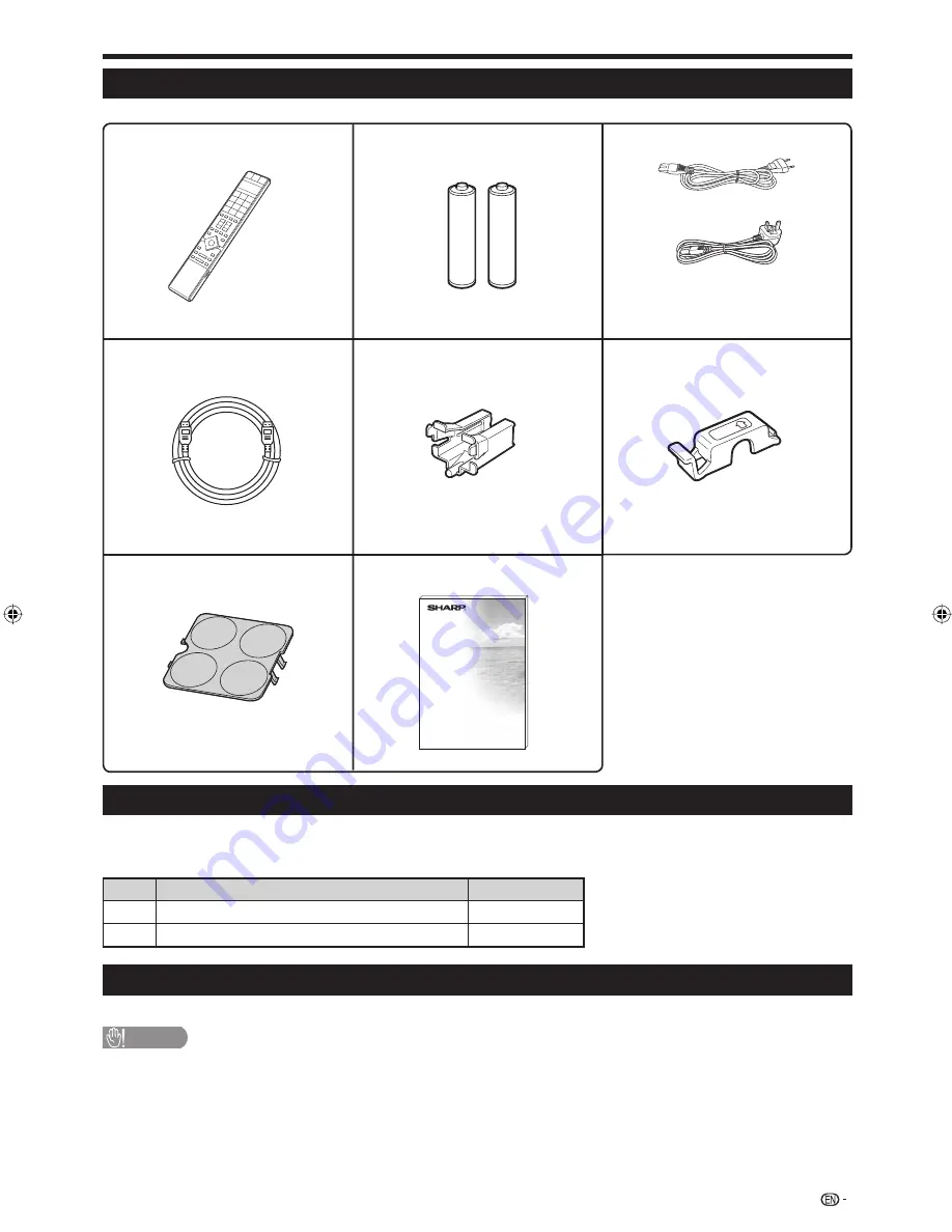
Supplied accessories

Optional accessories

The listed optional accessories are available for this LCD colour TV. Please purchase them at your nearest shop.

Additional optional accessories may be available in the near future. When purchasing, please read the newest catalogue for 
compatibility and check the availability.

No.

Part name

Part number

1

Wall mount bracket

AN-65AG2

2

Stand unit

AN-65ST1

Attaching the Stand

For details, refer to the installation manual of the optional stand unit.

CAUTION

This Display should be used only with the stand unit AN-65ST1 (SHARP). The use of other stand units may result in unstable 
installation and may cause serious injuries.

 5

HDMI cable fixture (

g

1)

Page 9

Remote control unit (

g

1)

Pages 3 and 6

“AAA” size alkaline battery 

(

g

2)

Page 6

HDMI cable (

g

1)

Pages 8 and 9

Operation manual

HDMI cable holder (

g

1)

Page 8

Power cord cover (

g

1)

This covers the compartment on the 

back of the Display after installing the 

wall mount brackets or stand units.

AC cord (

g

2)

Page 10

This cord is for regions other than 

Singapore.

This cord is only for Singapore.

LC-65XS1M_en.indd   5

LC-65XS1M_en.indd   5

2009/01/15   16:02:44

2009/01/15   16:02:44

Summary of Contents for Aquos LC-65XS1M

Page 1: ...C 65XS1M AVC System AVC 系統 AVC 系统 TU X1M LCD COLOUR TELEVISION 液晶彩色電視機 液晶彩色電視機 ENGLISH OPERATION MANUAL 使用說明書 使用說明書 LC 65XS1M OPERATION MANUAL 使用說明書 使用說明書 中文 繁體 中文 簡體 Printed in Japan 日本印刷 日本印刷 TINS D978WJN1 09P02 JA KG ...

Page 2: ......

Page 3: ...CO Settings 24 Channel Settings 25 Auto Installation 25 Password settings 26 Language Settings language 26 Teletext 26 Teletext language setting 27 Displaying Subpages 27 Time display 27 Displaying Subtitles 27 Updating your TV via USB 28 Useful Viewing functions 29 Selecting the picture size 29 Selecting the WSS picture size automatically 29 Selecting the WSS picture size manually 29 Selecting th...

Page 4: ...rts advise against extended listening at high volume levels To prevent fire never place any type of candle or naked flames on the top or near the TV set To prevent fire or shock hazard do not place the AC cord under the TV set or other heavy items Do not display a still picture for a long time as this could cause an afterimage to remain There is power consumption always if main plug is connected S...

Page 5: ...channel or input information Displays the time information included in the Teletext broadcast See page 27 OPC To switch the Optical Picture Control on and off See page 22 GALLERY Press to enter the Gallery Mode See page 32 SLP SLEEP Set the Seep timer See page 11 INPUT INPUT SOURCE Select an input source TV INPUT 1 INPUT 2 INPUT 3 INPUT 4 INPUT 5 INPUT 6 INPUT 7 PC See pages 11 and 31 IN1 IN2 IN3 ...

Page 6: ...inals REC OUT terminals ANT Antenna terminal DC OUTPUT terminal 8 9 10 11 12 DIGITAL AUDIO OUTPUT terminal INPUT 1 HDMI terminals INPUT 2 HDMI terminal RS 232C terminal 13 14 15 16 SERVICE ONLY terminal DISPLAY OUTPUT terminal AC INPUT terminal Usually do not connect anything to this terminal as it is reserved only for service personnel 17 18 19 Product label is on the bottom of the AVC System 4 V...

Page 7: ... refer to the installation manual of the optional stand unit CAUTION This Display should be used only with the stand unit AN 65ST1 SHARP The use of other stand units may result in unstable installation and may cause serious injuries 5 HDMI cable fixture g1 Page 9 Remote control unit g1 Pages 3 and 6 AAA size alkaline battery g2 Page 6 HDMI cable g1 Pages 8 and 9 Operation manual HDMI cable holder ...

Page 8: ... the reset button your universal remote control settings will be deleted The remote control unit has a internal memory of external devices In order not to lose the data replace the batteries quickly The batteries supplied with this product may have a shorter life expectancy due to storage conditions If you will not be using the remote control unit for an extended period of time remove the batterie...

Page 9: ...xternal devices such as a DVD recorder Cables and terminals may vary depending on the devices you use 3 Prepare remote control unit Page 6 Insert the supplied AAA size alkaline batteries into the remote control unit 4 Turning on and running the initial auto installation Turn on the TV power Page 11 Plug the AC cord into AC outlet Press POWER on the Display to turn on the main power of the Display ...

Page 10: ... cause serious injuries Installing the Liquid Crystal Television requires special skill that should only be performed by qualified service personnel Customers should not attempt to do the work themselves SHARP bears no responsibility for improper mounting or mounting that results in accident or injury Using an optional bracket to mount the Display You can ask a qualified service personnel about us...

Page 11: ...cloth beneath the AVC System or cover it with one as this can cause overheating and result in malfunction 5cm 5cm 5cm NOTE The POWER indicator of the AVC System lights up when the main power is turned on after connecting the Display and AVC System using the supplied HDMI cable The HDMI cable should be firmly connected Failure to do so will loosen the cable and cause a contact failure when moving t...

Page 12: ...on of the TV Press c d to select where you will use this TV and then press ENTER HOME STANDARD will be the default value for the AV MODE setting STORE DYNAMIC Fixed will be the default value for the AV MODE setting If the AV MODE is changed the TV will automatically switch back to DYNAMIC Fixed when there is no signal input from the TV or remote control unit for 30 minutes Auto installation will b...

Page 13: ...stem POWER indicator Status Off Power off Blue Power on Red Standby NOTE If you are not going to use this TV for a long period of time be sure to remove the AC cords from the AC outlet A small amount of electric power is still consumed even when POWER is turned off Changing channels With 0 9 With CH r s Auto power off at a designated time This function is conveniently used when for instance going ...

Page 14: ...B PAL PAL NICAM 01 TV TV BBC1 When receiving a monaural signal Each time you press MPX the mode switches between NICAM MONO and MONO Monaural mode B G MONO 01 BBC1 B G MONO PAL NICAM PAL 01 TV TV BBC1 In the TV mode of A2 TV broadcasts When receiving a stereo signal Each time you press MPX the mode switches between STEREO and MONO Stereo mode B G STEREO 01 BBC1 B G MONO PAL PAL 01 TV TV BBC1 When ...

Page 15: ... PC to the AVC System Introduction to connections The AVC System is equipped with the terminals as shown below Find the cable corresponding the terminal and connect the device NOTE The cables illustrated in pages 13 15 are commercially available items E S video cable When using an S video cable you also need to connect an audio cable R L 13 Audio VCR Page 15 Video recording device Page 14 Game con...

Page 16: ... accurate colour reproduction and high quality images through INPUT5 terminals or INPUT6 terminals when connecting a DVD player recorder or other device Y PB CB L R PR CR COMPONENT AUDIO S VIDEO VIDEO connection You can use INPUT4 terminals when connecting to a game console camcorder a DVD player recorder or other device NOTE When using an S video cable you also need to connect an audio cable R L ...

Page 17: ...N INPUT VIDEO R L Connecting a VCR E Connecting an amplifier with digital audio input E Speaker VCR connection Connect an amplifier VCR with external speakers as shown below 15 Optical audio cable AV cable VCR Amplifier with digital audio input ...

Page 18: ... LINK compatible audio system NOTE Point the remote control toward the TV not to the connected HDMI device Video noise may occur depending on the type of HDMI certified cable used Make sure to use a HDMI certified cable Up to 3 pieces of HDMI recording equipment and one AV amplifier can be connected using this system These operations affect the HDMI device selected as the current input source If t...

Page 19: ...lect Auto Power On and then press ENTER Press c d to select On and then press ENTER NOTE The factory default for this item is Off Selecting Recorder You can select a recorder for the recording from several connected recorders Repeat steps 1 to 3 in AQUOS LINK Control Press a b to select Selecting Recorder and then press ENTER 1 2 3 4 5 1 2 3 1 2 Select the recorder and then press ENTER NOTE If you...

Page 20: ...the programme to record You can use a b c d RTN RETURN EXIT and the coloured buttons NOTE Refer to the operation manual of the recorder for details 1 2 1 2 3 1 2 3 1 2 1 2 3 Operating an AQUOS LINK device AQUOS LINK allows you to operate the HDMI connected device with one remote control Open the remote control unit s flip cover Press PLAY I to start playback of a title See this page section Playba...

Page 21: ...n without a remote control unit This function is useful when there is no remote control unit within your reach Press MENU and the MENU screen displays Press CHs r instead of a b or VOL l k instead of c d to select the item Press INPUT to complete the setting NOTE The MENU screen will disappear if left unattended for several seconds 1 2 3 About the Guide Display The Guide Display at the bottom of t...

Page 22: ... Page 24 No Signal Off Page 24 No Operation Off Page 24 Auto Installation Page 25 Programme Setup Page 25 Child Lock Page 26 Input Skip Page 31 Input Label Page 31 Position Page 30 HDMI Auto View Page 30 WSS Page 29 4 3 Mode Page 29 Language Page 26 Text Language Page 27 Software Update Page 28 Identification Page 39 Reset Page 39 Gallery Setup Page 32 AQUOS LINK Setup Pages 16 18 HDMI Audio Selec...

Page 23: ...Audio Treble Page 23 Bass Page 23 Balance Page 23 SRS TS XT Page 24 Sound Mode Page 24 Reset Page 23 ECO Energy Save Page 24 No Operation Off Page 24 Setup Input Skip Page 31 Input Signal Page 35 Auto Sync Page 35 Input Label Page 31 Position Page 30 Fine Sync Page 35 Language Page 26 Reset Page 39 Option AQUOS LINK Setup Pages 16 18 Auto Volume Page 30 Audio Only Page 30 Game Play Time Page 30 Se...

Page 24: ...rightens Contrast For less contrast For more contrast Brightness For less brightness For more brightness Colour For less colour intensity For more colour intensity Tint Skin tones become purplish Skin tones become greenish Sharpness For less sharpness For more sharpness Advanced Picture High White with bluish tone Mid High Intermediate tone between High and Middle Middle Natural tone Mid Low Inter...

Page 25: ...viewing NOTE 3D Y C may not operate depending on the input signal type or when the input signal is noisy 3D Y C has even more effect on composite video signals CVBS Active Contrast Automatically adjusts the contrast of an image according to the scene Gamma setup Select the tone difference of the brightness and darkness of the picture according to the type of programme watched from the four items M...

Page 26: ...theatre Sound Mode Audio This function allows you to select the sound mode depending on the type of programme watched Standard Reduces the backlight brightness by 20 Advanced Reduces the backlight brightness by 30 Off The backlight brightness is the same value of your settings in the selected AV MODE NOTE This function does not work when AV MODE is set to DYNAMIC Fixed Energy Save status icons Ico...

Page 27: ... press ENTER Press a b c d to move it to the desired position and then press ENTER Repeat steps 2 and 3 until all desired channels are sorted Erase Programme Channels can be erased individually Press c d to select Yes and then press ENTER Press a b c d to select the channel you want to erase and then press ENTER A message window pops up Press c d to select Yes and then press ENTER to erase the sel...

Page 28: ...g market Teletext mode Teletext is turned on off with m on the remote control unit You can operate your TV in Teletext mode directly by inputting commands with the remote control unit Turning on and off Teletext Select a TV channel or external input source providing the Teletext programme Press m to display the Teletext Press m again to display the Teletext on the right screen and normal image on ...

Page 29: ...ge as shown below Subpage screen 1 2 Time display You can display the time information included in the Teletext broadcast Select a TV channel providing Teletext information The time information is automatically captured Press DISP The channel display will appear on the display Press DISP again within the three seconds interval the channel display is on the screen Time information will display on t...

Page 30: ...software update file 5 CAUTION Be sure to insert the USB device correctly into the terminal of device you select in step 4 The TV displays a confirmation screen while checking the data in the inserted USB device Checking Now checking the data in the USB memory device CAUTION If the data is not compatible with the system an error message appears on the screen Repeat steps 5 and 6 after pressing ENT...

Page 31: ...ull For 16 9 squeeze pictures Cinema 16 9 For 16 9 letterbox pictures Bars may appear on the top and bottom with some programmes Cinema 14 9 For 14 9 letterbox pictures Bars may appear on the top and bottom with some programmes Full Displays with an Overscan image Crops all sides of screen Underscan Displays with an Underscan image only when receiving a 720p signal Displays with the High Definitio...

Page 32: ...tening to music from a music programme you can set the TV off and enjoy audio only Useful Viewing functions H Pos Centres the image by moving it to the left or right V Pos Centres the image by moving it up or down Off Both screen images and audio are output On Audio is output without a screen image Game Play Time Option This function allows you to display the elapsed time on the screen when AV MOD...

Page 33: ...than six characters select END to set the name INPUT SOURCE TV INPUT1 INPUT2 INPUT3 INPUT4 INPUT5 DVD INPUT7 NOTE You cannot change labels if the input source is TV 1 2 3 4 Input Skip Setup This setting allows you to skip INPUT1 3 or INPUT7 on the Input Source Selection operation INPUT 1 HDMI INPUT 2 HDMI INPUT 3 HDMI INPUT 7 RGB Yes No Colour system settings You can change the colour system to on...

Page 34: ...isplay from performing correctly NOTE Make sure that a USB device is connected before pressing GALLERY The playback order is based on the file names and cannot be changed The device contains up to 100 files If there are more than 100 some may not be displayed The picture files should be in the top directory and the files in any subordinate folders cannot be displayed Refer to the right column Gall...

Page 35: ...en you see the error message Possible Solution Images that do not conform to the DCF 2 0 specification may not be displayed If the images have been changed or edited on a PC the data may change to a format that is incompatible with the TV The file size may be over 6MB The file size can be reduced by selecting a smaller pixel size when taking pictures with a digital camera The resizing function of ...

Page 36: ...e picture size Press WIDE WIDE MODE The WIDE MODE menu displays Press WIDE WIDE MODE or a b to select a desired item on the menu NOTE Connect the PC before making adjustments Selectable picture size may vary with input signal type a 1 2 Normal Keeps the original aspect ratio in a full screen display Cinema For letterbox pictures Bars may appear on the top and bottom with some programmes Full An im...

Page 37: ...uccessful Auto Sync completed successfully displays If not Auto Sync failed Auto Sync may fail even if Auto Sync completed successfully displays Auto Sync may fail if the PC image has low resolution has unclear black edges or is moved while executing Auto Sync Be sure to connect the PC to the AVC System and switch it on before starting Auto Sync Auto Sync can be executed only when inputting analog...

Page 38: ...the RS 232C terminal The input signal PC video can be selected the volume can be adjusted and various other adjustments and settings can be made enabling automatic programmed playing Use an RS 232C serial control cable cross type commercially available for the connections NOTE This operation system should be used by a person who is accustomed to using PCs Parameter Input the parameter values align...

Page 39: ... nn C L C K _ CLOCK 0 180 P H S E _ PHASE 0 40 WIDE MODE W I D E 0 _ _ _ TOGGLE AV W I D E 1 _ _ _ NORMAL AV W I D E 2 _ _ _ ZOOM 14 9 AV W I D E 3 _ _ _ PANORAMA AV W I D E 4 _ _ _ FULL AV W I D E 5 _ _ _ CINEMA 16 9 AV W I D E 6 _ _ _ CINEMA 14 9 AV W I D E 7 _ _ _ NORMAL PC W I D E 8 _ _ _ CINEMA PC W I D E 9 _ _ _ FULL PC W I D E 1 0 _ _ DOT BY DOT AV PC W I D E 1 1 _ _ UNDERSCAN AV MUTE M U T...

Page 40: ...ressed e Mute on the remote control unit The TV sometimes makes a cracking sound This is not a malfunction This happens when the cabinet slightly expands and contracts according to changes in temperature This does not affect the TV s performance Cautions regarding use in high and low temperature environments When the TV is used in a low temperature space e g room office the picture may leave trail...

Page 41: ...Press and hold both CHr and VOLk on the Display simultaneously until the message appears on the screen 1 2 3 You can check the TV ID on the screen for reporting to customer service Picture maintenance When you set your TV for a long period of time colour shading on the screen may appear due to degradation of the LED backlight You can control the colour shading after performing Picture maintenance ...

Page 42: ...iamond 104 105 Digitor 160 DK Digital 032 176 Dmtech 111 Dual 001 103 D Vision 034 DVX 105 Easy Home 107 Eclipse 104 Elta 034 124 134 Emerson 129 Enzer 103 Euroline 034 Finlux 104 Fisher 132 Global Solutions 105 Global Sphere 105 Go Video 126 GoldStar 015 Goodmans 001 014 018 045 106 109 158 203 228 Graetz 103 Grundig 018 038 099 109 127 H B 106 156 Haaz 104 105 Harmon Kardon 144 HE 001 HiMAX 107 ...

Page 43: ...nada 026 054 057 059 063 071 120 123 126 Grandin 021 026 049 052 053 055 058 059 061 072 Grundig 009 041 054 055 057 069 070 071 074 075 076 090 125 149 150 153 173 179 181 182 187 Hanseatic 053 054 059 061 Hantor 058 Harwood 055 HCM 055 075 Hinari 045 051 055 056 060 061 075 127 Hisawa 045 051 166 Hitachi 005 016 019 026 049 050 054 056 060 098 115 120 123 126 149 150 153 175 185 Hypson 051 055 0...

Page 44: ...52 Ferguson 068 076 158 327 328 335 336 004 037 043 108 118 Fidelity 050 079 098 Finlandia 071 001 037 Finlux 071 091 156 329 340 003 037 111 126 Flair Mate 004 Foxtel 059 064 065 Fracarro 167 305 313 331 334 001 141 Freecom 022 050 002 036 128 Freesat 060 097 FTE 088 094 160 291 308 337 002 109 130 FTEmaximal 004 049 Fuba 022 044 049 071 088 089 274 285 300 334 009 036 039 040 110 112 116 125 126...

Page 45: ... 044 051 053 090 098 101 001 040 Variosat 020 022 Vega 049 Ventana 077 001 139 Vestel 101 Viasat 066 Visionic 062 Visiosat 004 056 100 041 042 147 148 Viva 078 Vivid 064 Vortec 032 321 334 001 036 VTech 057 001 115 082 100 114 Wela 094 Welltech 047 WeTeKom 047 050 052 Winersat 083 305 313 324 331 001 041 Wintergarten 080 WINTERNITZ 279 288 Wisi 020 022 050 053 082 089 094 100 116 178 185 190 191 1...

Page 46: ...80P 576P 720P 50Hz 720P 60Hz 1080I 50Hz 1080I 60Hz 1080P 50Hz 1080P 60Hz 1080P 24Hz AUDIO in Ø 3 5 mm jack INPUT 2 HDMI HDMI input 480I 576I 480P 576P 720P 50Hz 720P 60Hz 1080I 50Hz 1080I 60Hz 1080P 50Hz 1080P 60Hz 1080P 24Hz INPUT 5 VIDEO in AUDIO in COMPONENT in 480I 576I 480P 576P 720P 50Hz 720P 60Hz 1080I 50Hz 1080I 60Hz INPUT 6 VIDEO in AUDIO in COMPONENT in 480I 576I 480P 576P 720P 50Hz 720P...

Page 47: ...Appendix Dimensional drawings 1528 1428 5 1312 1046 598 803 5 933 113 60 4 47 1 22 8 400 400 314 Unit mm LC 65XS1M 430 318 71 TU X1M The depth does not include the protruding part of terminals 45 ...

Page 48: ...Appendix NOTE As a precautionary measure make a note of your password above remove it from this manual and keep it in a familiar place The Password is 46 ...

Page 49: ......

Page 50: ......

Reviews: